Aircraft General Knowledge (AGK)
For a live overview of my flight lessons, visit: https://flighttools.justinverstijnen.nl/flightlessontracker
This page can contain a collection of personal notes, steps to remember, finished and unfinished content. Please excuse brevity.
Do not use specific information given like fuel flow, landing/take-off distances for your flights. Always refer to the POH of your exact plane for flight preparation. My information is just for references that I used.
The airframe (1)
The frame of a plane consists of several parts, which all make flying and steering in the air possible by various actions. I will describe all parts in English and Dutch:
- Wing - Vleugel -> The horizontal part which makes flying an aircraft possible in the first place by generating lift
- Aileron - Rolroer -> These are the parts at the end of the wings, making roll-turns (banking) possible. They are at the end of the wing due to force x moment
- Elevator - Hoogteroer -> This part controls the pitch attitude of the aircraft, making the nose move up or down.
- Rudder - Richtingsroer -> This part at the end of the tail controls yaw and is used to keep the aircraft coordinated and make directional corrections.
- Flaps - Landingskleppen -> These are parts on the wing which can be used in take-off and landings to fly at lower speeds nearby the ground. They extend to induce more drag, which equals a lower speed and they generate some lift
- Vertical stabilizer - Kielvlak -> This is the standing part of the tail of an airplane, giving directional stability around the yaw axis.
- Horizontal stabilizer - Stabilo -> This is the horizontal part of the tail of an airplane, giving stability around the pitch axis.
Aircraft construction
The aircraft itself can be constructed in several different ways. The most important thing here is the type of aircraft. Bush planes are very light and will be less likely to use heavy stainless steel.
- Monocoque: A construction method where the external skin of the aircraft carries almost all of the loads. There is little or no internal framework. It’s lightweight but can be less tolerant to damage, since the skin itself is the main structure.
- Outside supports all forces
- Comparable with a can of coke
- Semi-monocoque: A more common design in modern aircraft. The external skin still carries loads, but it’s reinforced by an internal structure (frames, stringers, bulkheads). This makes the structure stronger, more damage-tolerant, and easier to repair than pure monocoque.
- Inside supports half of the forces and outside half of the forces
- Truss contruction: This method will support all forces on the inside of the plane. Here the outside could be any material, like leather or vinyl.
- Inside supports all of the forces
The wings
We could have two types of wings:
- Cessna 172 has the wings above the cockpit: high-wing (hoogdekker)
- The Cessna 172 uses strut-braced wings.
- Piper PA-28 has the wings below the cockpit: low-wing (laagdekker)
- The Piper PA-28 has cantilever wings, meaning there is no external strut support.
- These wings are often set in a V shape, called dihedral
Both of this types of planes have their pro’s and cons. In many Cessna 172 versions, the high-wing fuel tanks allow fuel to flow by gravity. Some aircraft versions and fuel systems can still have fuel pumps, so always check the POH of the exact aircraft. Als we cannot see traffic above us very good in a Cessna, but not very good under us with a cantilever wing.
There are also planes which have a V shaped tail with a rudder and elevator combined. These types of tails are called a ruddervator.
Tires
We can have 2 types of tyres on arplanes:
- Tube-type: This type has an inner tube and an outer tyre, comparable with a bicycle tyre.
- Can be sensitive to tube damage if the tyre slips on the rim.
- Often has a slip mark to detect movement between tyre and rim.
- Tubeless: This type has no separate inner tube.
Tyres can slip over the rim during landings, this is the reason maintenance does a little slipmarker on the tyre and rim. This is mostly red. The purpose of this marker is to see within seconds if the tyre has been slipped over the rim during earlier landingd, which comes with possible unclear damage.
Nose wheel construction
The shockdamper of the nose wheel construction works with gas and oil, which have both a unique task:
- Gas for suspension (vering)
- Oil for damping
The gas, usually nitrogen, provides the spring effect because it can be compressed. The oil provides damping because it is forced through small openings or chambers. Oil itself cannot be compressed, but it can control the speed of the movement.
The nose wheel also has:
- Shimmy damper: which is a device that helps preventing the nose wheel from vibrating very aggressively during high speeds on the ground. If a shimmy happens, the wheel can shake like a bike where you let go of the steer
- Torque link: The torque link (torsieschaar) is a device that prevents the nose wheel from rotating outside of its steering range, so keeps it aligned with the planes’ heading
Hydraulic systems
Hydraulic means transferring pressure by using an incompressible fluid. In aircraft this is hydraulic fluid, not water which properties are that it can be hardly compressed, as a low viscocity and is dangerous for human people to touch with hands and eyes. This fluid is pumped around like a circuit, where the circuit is leveraging the least resistance at the action, like a brake so if you press on the brake pedal, this force is transferred to the brake at the wheel en from there the fluid is pumped pack to the reservoir and the brake pedal.
We can transfer different forces using liquids hydraulically using this formula:
- Force = Pressure × Area (F = P × A)
This means that, at the same pressure, a larger surface area gives a larger force. Liquids are a great way to transfer force, as fluids can hardly be compressed compared with air.
Hydraulic liquids properties are:
- Unhealthy then touched
- Thin and low viscocity
Much systems in an airplane works with hydraulic systems, like:
- Brakes
- Landing Gear
- Propellor blade angle
Brakes
Brakes are systems built on the axes of the airplane to brake it, to lose power. This process converts the kinetic energy of the plane into energy in the brakes, which is warmth. Brakes are mostly powered using hydraulics.
Icing
As we don’t want ice on our plane or in parts of the plane, we have ice-preventing systems as we know two different categories:
- Anti-icing (prevent): Systems that prevent ice from happening like windshield anti ice, engine anti-ice, carb heat or the pitot heat
- De-icing (revive): Systems that remove ice that has already built up, like pneumatic boots on the leading edge of the wings or stabilizers.
Both systems are being used to battle ice during flights.
Fire and smoke in the plane
There are situations that fire and smoke can happen in the cockpit. Let’s dive into the different scenarios.
Engine fire during start
During starting the engine, engine fire can happen. This is mostly because of overpriming the engine, having way too much excess fuel that ignites instantly. Also priming with the throttle which pumps fuel into the carburetor, increases the chance of engine fire.
The actual procedure to follow during this situation is specific to your aircraft but the base is something like this:
- Continue cranking for 5–10 seconds to try to suck the flames into the engine
If engine starts:
- Parking brake set
- 1700 RPM
- Prepare seatbelts, doors, fire extinguisher
- Wait max. 2 minutes/120 seconds
- If fire continues:
- Mixture cut‑off
- Throttle full open
- Fuel selector OFF
- Ignition OFF
- Master switch OFF
If engine does not start:
- Mixture cut‑off
- Throttle full open
- Continue cranking briefly
- Ignition OFF
- Master switch OFF
- Fuel selector OFF (if possible)
- Extinguish fire using any possible method
Smoke in the cockpit
Smoke can happen in the cockpit due to several causes:
- Short-circuit in the electrical system
- Disable the complete electrical system and turn off electrical components one by one with the circuit breakers till you found the problem
- Engine fire
- Follow the POH/checklist of the exact aircraft. In general, the goal is to stop the fuel supply, reduce the chance of fire entering the cockpit, and prepare for an emergency landing.
- Other parts on fire
To correctly battle these situations, we must first know what to do exactly in each situation. These are described in the POH of your aircraft. For fires in flight, a CO2 extinguisher is the best option.
Fire types and extinguishers
Maintaining a fire is done by having these three components:
- Fuel (flammable material)
- Oxygen
- High temperature
By taking away only one of these three components, the fire will extinguish. We have four types of fire with possible extinguish methods:
- A = Solid materials like wood, paper, textile and some plastics
- Often water, foam or dry powder
- B = Flammable liquids like gasoline or oil
- Foam, dry powder, CO2 or Halon/Halon replacement, depending on the situation
- C = Gas fires
- Stop the gas supply if possible, then use a suitable extinguisher
- D = Metal fires, like magnesium or aluminium powder fires
- Special dry powder extinguisher for metal fires
- F = Fat or cooking oil fires
- Wet chemical extinguisher
Water based extinguishers are not that practical for electrical and type B fires. Water is heavier than fuel. Also, Halon extinguishers are very poisonous so good ventilation is needed when using these. This also counts for CO2 type extinguishers, which are generally not for closed environments.
The piston engine (2)
In planes, the most used engine type is a four-stroke (viertakt) gasoline engine. Four strokes means that the engine uses 4 strokes to complete the fuel burn process. The engine is obviously the most important part of getting the propellor to turn.
The engine has the following parts:
| Dutch term | English term | Explanation |
|---|---|---|
| Carburateur | Carburetor | A part of the engine that mixes fuel and air to create the correct fuel-air mixture for combustion. |
| Inlaat | Intake | The part of the engine where the fuel-air mixture enters the cylinder. |
| Inlaatklep | Intake valve | A valve that opens and closes at the correct moment to let the fuel-air mixture flow from the intake into the combustion chamber. |
| Uitlaat | Exhaust | The part of the engine where the burnt gases leave the cylinder and are guided toward the main exhaust system. |
| Uitlaatklep | Exhaust valve | A valve that opens and closes at the correct moment to let the burnt gases leave the combustion chamber through the exhaust. |
| Bougie | Spark plug | The part that ignites the fuel-air mixture by producing an electrical spark. |
| Nokkenas | Camshaft | This part is connected to the crankshaft by gears or a timing system. It controls when the intake valve and exhaust valve open and close. In a four-stroke engine, the camshaft rotates at half the speed of the crankshaft. |
| Cilinder | Cylinder | The cylinder is the main chamber in which the piston moves up and down. Combustion takes place in the upper part of the cylinder. |
| Verbrandingsruimte | Combustion chamber | The area where the fuel-air mixture is compressed and ignited. This is where combustion takes place. |
| Zuigerveren | Piston rings | Rings attached around the piston. Their purpose is to seal the combustion chamber from the rest of the cylinder and to help control oil. |
| Zuiger | Piston | A moving part inside the cylinder. It is connected to the crankshaft through the connecting rod and transfers the force from combustion into mechanical movement. |
| Drijfstang | Connecting rod | The part that connects the piston to the crankshaft. It transfers the up-and-down movement of the piston to the crankshaft. |
| Krukas | Crankshaft | The crankshaft converts the up-and-down movement of the piston into rotating movement. In an aircraft engine, the propeller is connected to the crankshaft. In a car, the crankshaft ultimately drives the wheels through the drivetrain. |
| Carter | Oil sump / oil pan | The lower part of the engine that contains engine oil. It stores oil that is used to lubricate the moving parts of the engine. This can be a wet sump or a dry sump system. |
| Krukkast | Crankcase | The central housing of the engine. It contains and supports the crankshaft and often also parts of the camshaft system. At the bottom of the crankcase there is usually an oil sump or oil pan, which contains engine oil. |
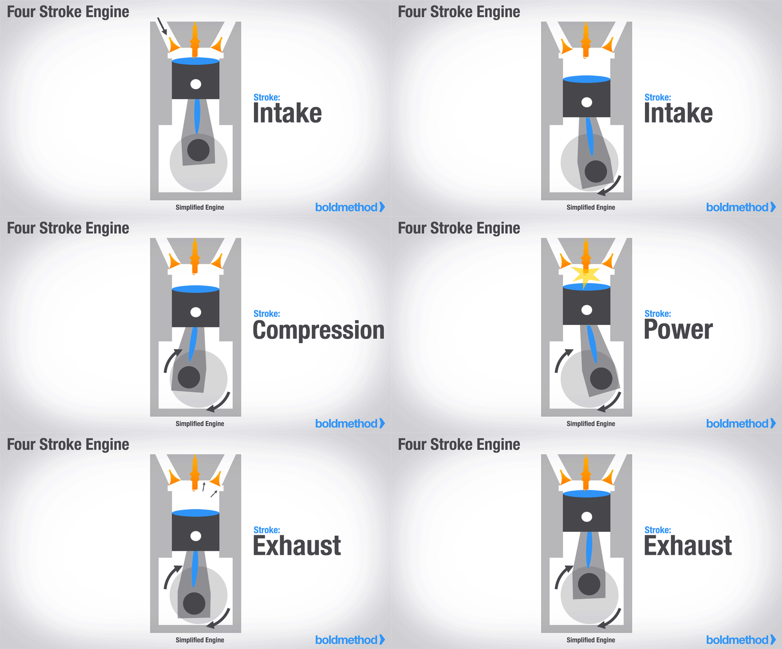
Burning fuel in a 4 stroke engine is completed in 4 different phases:
- Inlaatslag (Intake)
- Compressieslag (Compression
- Arbeidsslag (Power)
- Uitlaatslag (Exhaust)
Engine shapes
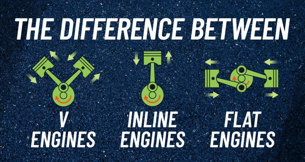
There are multiple types of motorshapes. In planes, the most used shapes are:
- Line engines
- Horizontally opposed engines, often called boxer engines
Engine power units
The units which can be used to measure engine power are mostly indicated in Horse Power (HP/pk). This is a worldwide standard, but sometimes the actual measurement method is described. Sometimes BHP % is used in the POHs of the aircraft. The method to measure is a special installation connected to the crankshaft, and measuring the force needed.
We also have an indication of how long you may use full engine power. The indicator for maximum continious power is the maximum power you can use unlimited. In fixed-pitch propeller aircraft, RPM gives an indirect indication of engine power. In constant-speed propeller aircraft, power is normally managed using manifold pressure and RPM together.
At bigger heights, like from 3000ft, we need to pull somewhat on the mixture handle to reduce the amount of fuel going into the engine. At bigger altitude, the process is more inefficient when putting too much fuel into the engine.
- Manifold pressure: The absolute pressure in the intake manifold, usually measured downstream of the throttle valve.
- Brake horsepower (BHP): The actual power delivered at the engine output shaft, measured with a dynamometer or brake system.
The power of a piston engine depends on the air density. This is depending on the pressure, temperature and humidity. At a low air density
Turbo-engines can be described in different ways:
- Turbo-normalized: This type helps the engine maintain about sea-level manifold pressure at higher altitude.
- Turbocharged: This type can increase manifold pressure above normal sea-level pressure, depending on the engine design and POH limits. This works till the critical altitude.
How a turbo system works
A turbo system is basically a turbine and a compressor. The turbine is driven by the exhaust gasses and is connected through an axis with the compressor which is placed in the air inlet system. The compressor will increase the pressure of the intake air, resulting in a higher manifold pressure. This increases the motor-power. Turbine compressors rotate at a very high RPM, around 80.000 RPM to 100.000 RPM in some cases.
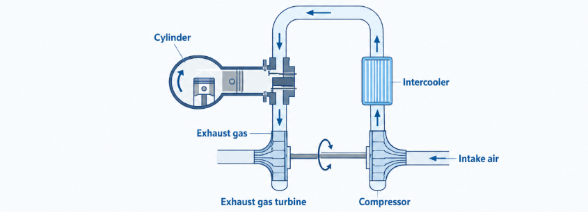
The schematic drawing of a turbine-compressor combination.
As a result of the compressed intake and the flow of hot exhaust gasses, the temperatures of a turbo will increase very high. Turbo’s can even be glowing red. Turbo engines therefore often have a intercooler, which cools the compressed intake air before it enters the engine. This is similar to a radiator. Turbo engines also need some minutes of stationary running before shutting down to completely cool down.
A waste gate is a valve in the exhaust system where part of the exhaust gases can bypass the turbine to control turbocharger speed and manifold pressure. Some engines have a automatic waste gate function, in these type planes you can use full power on sea level.
Multi engine planes
There are also planes with multiple engines. They have engines which have separate systems to power and provide fuel to those engines. This is by design to minimize the chance of having both engines to be in error at the same time.
- Multi-engine airplanes have rudder trim to compensate for single engine failures
- If a multi engine plane has one engine failure, they set the propellor to “feather” (vaanstand) to reduce the drag of the propellor
Fuel System (3)
The fuel system and parts of aircraft are categorized into two categories:
- The fuel tanks with the fuel lines to the engine
- The induction system to merge the fuel with air where two types are possible
The fuel system can consist of the following possible parts:
- One or more fuel tanks conistsing tap-points with air vents amd cross-lines
- A fuel selector valve to select a specfiic tank or to open both or close both
- Fuel pumps
- Primer system
Fuel tanks are very often located in the wings, but can also be in the wingtips or fuselage parts.
The goal of the fuelsystem is to drive fuel to the carburetor, where the fuel and air mixture is created before being ignited in the cylinders. If fuel tanks are located above the carburetor, like in many carbureted Cessna 172 aircraft, fuel can flow due to gravity feed. Some aircraft versions, especially fuel-injected versions, can still have fuel pumps, so always check the POH.
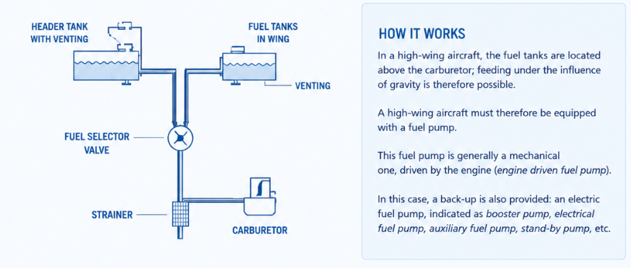
On planes where the fuel tanks are on the same level or lower than the carburetor, the fuel needs a pump to do the work. This pump is mostly driven mechanically by the engine. For backup purposes, in most cases we also have a electronic fuel pump which is often called a stand-by pump or auxillary fuel pump.
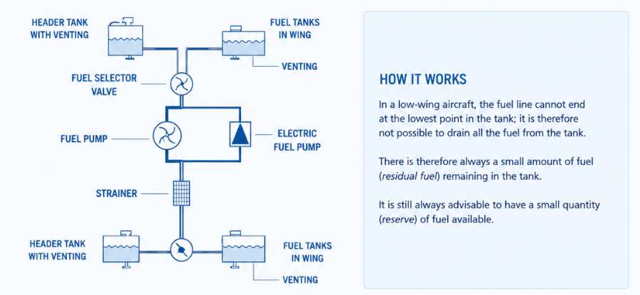
The fuel output point in the fuel tank is in most cases at the lowest point of the tank. However, we lose some part of the fuel making the difference between all fuel and unusable fuel. On the Cessna 172, we lose around 1,5 USG because of this. The pro of this is that possible dirt and other contamination is sinking to the bottom and not injected into the fuel system.
Fuel venting system
Fuel tanks have a venting system to maintain atmospheric pressure in the tank as fuel is used and as pressure or temperature changes. This is very critical at high-wing planes to ensure fuel always flows to the engine due to gravity. If the vent becomes blocked, a vacuum can form in the tank and fuel flow to the engine can be restricted or stopped. Types of venting are:
- Venting pipes in the tank itself
- Special tank caps
Fuel tanks also have a drain at the bottom side, which can be used if any contamination or water is in the fuel and the color can be checked. Here we also have a strainer where water and contamination can be removed from the tank.
Vapour lock
Vapour lock is a phenomenon where fuel vapour bubbles occur in the fuel lines, making the fuel flow very hard or sometimes even impossible. It can be caused by high temperatures, low pressure in the fuel system, or fuel with a higher vapour pressure. To solve vapour lock, turn on the electrical fuel pump and/or enhance engine cooling, according to the POH. Using Mogas fuel can increase the chance of vapour lock compared with AVGAS. The chance of this happening is therefore higher on hot summer days.
Fuel selectors
Fuel selector valves are being used to select where the fuel comes from. By setting this switch, you actually turn a mechanical valve to decide the flow of fuel. In most cases, we set this on both (if applicable) but in some cases to check or to balance the fuel in both tanks we select one of the two tanks only.
Fuel filters
In a piston engine, the fuel filter is placed between the tank and the fuel pump/primer so the fuel is cleaned before it reaches sensitive parts.This protects the fuel pump and primer from dirt, rust, water, or debris coming from the tank. If the filter were placed only after the pump, contaminated fuel could already damage or block the pump. Clean fuel also helps prevent blocked primer lines, poor starting, rough running, or fuel starvation. So the main reason is protection and reliable fuel flow to the engine.
Carburation
To let a piston engine work, the mixture of fuel and air must be optimal before being delivered to the cylinders. This mixture can be made using two different systems:
- Carburetor system
- Injection system
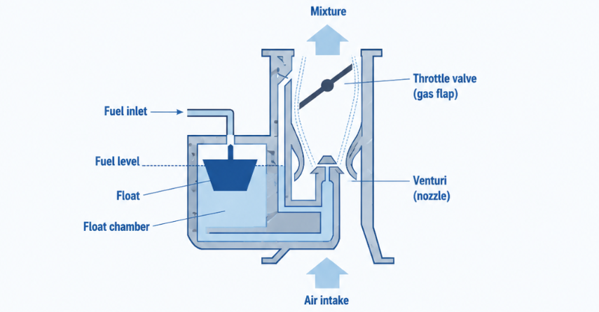
In the carburetor, air and fuel are mixed into a optimal ratio and then will be delivered to the engine cylinders. The carburetor consists of a pipe with a narrowing, the venturi, and a throttle valve which you control with the throttle handle in the cockpit. In the venturi is a sprinkler which is connected to the float-chamber. This system is also called a updraft carburetor
Fuel to air ratio
Chemically, combustion is a reaction of a particle with oxygen. To start a combustion, fuel must be combined with air in a specific ratio. When one of both is too less, no combustion can happen, so the combustion area of an engine is within a certain area.
For gasoline, the chemically ideal mixture is about 1 part fuel to 14,7 parts air by mass. This is called the stoichiometric ratio and is about 6,4% fuel by mass.
- Rich mixture: 1:8 or 11,1% fuel
- Lean mixture: 1:20 or 4,8% fuel
In engine descriptions, the version with the ratio is almost always used as where the percentage does make more sense. We need to control the mixture because we can fly in air with a lot of air molecules close to the ground but also in air high up with way less molecules. In real engine operation, the mixture is not always kept exactly at 1:14,7. For high power settings, a richer mixture is often used for power and cooling. In cruise, the mixture can be leaned according to the POH and engine limitations.
Additional carburetor parts
The carburetor contains some additional parts to make it work as expected:
- Idle sprinkler (nullastsproeier): This part ensures enough fuel is sprinkled during idle power, otherwise the engine will stop working
- Acceleration pump : When the throttle value is opened up quickly during acceleration, the sprinkler will start somewhat slower making the engine not run optimal. Some carburetors are equipped with a accelerationpump, pumping extra fuel into the carburetor, solving this problem
- Mixture-handle: The mixture handle itself controls the amount of fuel that is mixed with the air. As you push it forward towards Rich, you get a rich mixture, meaning much fuel per air molecule. By pulling the mixture, this amount will be decreased
- Idle cut-off valve: The plane also has a mixture handle that can be fully pulled to idle cut-off. This means the idle spinkler and carburetor are both disconnected from the fuel, and the engine to lose fuel resulting in a shutdown of the engine. This is the common way to turn off a planes’ engine in general aviation
- Power enrichment system: This system ensures in throttle full-scenario’s, the fuel is somewhat more rich to help the engine cool more efficiently. Excess fuel is used to cool the cylinders
Air inlet system
Air normally reaches the carburetor through the engine air inlet system. This inlet is located at the front of the aircraft, just below the propeller. Before the air reaches the carburetor, it passes through an air filter. This inlet or filter can become blocked by debris, grass, snow, ice, or other contamination, which is why inspecting the air inlet and filter area is part of the preflight inspection.
On carbureted Cessna 172 models, an alternate source of air is provided through the carburetor heat system. When the carb heat control is pulled in the cockpit, a valve in the carburetor air box changes position. Instead of using the normal filtered outside air, the engine draws warmer, unfiltered air from around the exhaust heat muff.
This warm alternate air helps prevent or remove carburetor ice. It can also allow the engine to keep running if the normal air inlet or air filter becomes blocked. However, because the air is warmer and less dense, using carb heat usually causes a drop (~10%) in engine power and RPM. Therefore, carb heat should be used according to the aircraft checklist and operating procedures.
- Carb heat off: Filtered air from outside
- Carb heat on: unfiltered air from the exhaust
Icing in carburetors
The moisture in the air can freeze in the carburetor if the temperature there is below 0 degrees. The temperature in the carburetor is always lower than the outside air temperature, because of the following reasons:
- Vaporizing of fuel: Vaporizing fuel costs energy and this is picked from the air, causing the temperature of the air to drop
- Lower pressure in the venturi: Lower pressure means a decrease in temperature
This is the reason we use carburetor heat according to the POH/checklist. In my flight lessons, the practical rule is to use carb heat when reducing power below 2000 RPM, except on the ground:
- In the full circuit
- During landing
- During descending
- During gliding
Carb icing can happen at any outside air temperature, even on hot and sweaty days:
- High humidity: The more moist in the air, the more can be frozen
- Low engine RPM: less heat is more ice
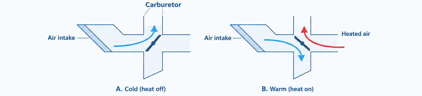
We check carb heat during the before take-off checklist by setting the RPM as specified in the POH, often around 1700 RPM, and then selecting carb heat ON.
- If there is no carb ice, RPM normally drops because the engine receives warmer and less dense air.
- If carb ice is present, RPM may first drop and then increase again as the ice melts.
- When carb heat is selected OFF again, RPM should normally return to the original value.
During the flight, we can recognize carb icing due to these causes:
- Reduce in Engine RPM
- Reduce in manifold pressure (constant speed propellor planes only)
- Very inconsistent running engine
Other rules about the Carb heating system are:
- Disable it (OFF) mostly on the ground, due to unfiltered air
- Disable it during climbs and go-arounds to get the best engine performance
- Enable or disable Carb Heat, no in between settings
- Carb Heat on means higher fuel usage
- Carb heat on means a higher fuel-air mixture, as less air comes in, the ratio has more fuel
Fuel injection
Carburetors have two important downsides:
- Icing in the venturi, possibly causing dangerous situations if not handled properly
- Fuel/air mixture distribution over cylinders is not equal
These problems can be solved by using fuel injection. This system, which is available in modern aircrafts, has an injection in every cylinder controlled by a fuel control unit in between.
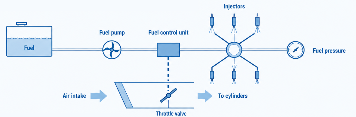
Just like the older carburation system we have a throttle valve, controlling the airflow into the engine. The fuel control unit meters the correct amount of fuel and sends it to the fuel divider and injectors. Most gasoline-based engine will inject the fuel continuously, not only when busy in the intake stage.
Fuel injection systems are always equipped with two possible ways of pumping fuel, which can be mechanical, using gravity or electrical. In the fuel manifold the fuel flow is measured, just like described in the disgram above.
Fuel injection systems are more complex and more expensive than carburetor systems, and they remove the risk of carburetor icing. However, induction icing or intake blockage can still be a risk, so some aircraft still have an alternate air system.
Aircraft fuel types
In aviation we know three types of fuel, each for their own cause.
| Fuel type | Description | Used for aircraft type |
|---|---|---|
| Mogas | Automotive gasoline, only usable in aircraft if approved by the engine/aircraft manufacturer or by STC | Some approved piston aircraft |
| AVGAS 100LL | Leaded aviation gasoline, blue in color | Many gasoline piston aircraft |
| AVGAS 91UL | Unleaded aviation gasoline with a lower octane rating than 100LL | Approved gasoline piston aircraft |
| Jet-A1 | Kerosene-type turbine fuel | Jet aircraft, turboprops and some diesel piston aircraft |
An important parameter of fuel for planes is the knock resistance (klopvastheid). Fuel with a low knock resistance can burn under high pressure and normal operating temperature, leading to detonation. This is called detonation and results in a rough running engine.
Most planes can, some with some revisions, run on both AVGAS and MOGAS. The primary reason to use one of the two is the price. At this moment, the prices in the Netherlands are around:
- AVGAS: 3,94 per liter
- Mogas: 2,63 per liter
Fluids themselve cannot burn. They first have to vaporize and the vapor needs to have a specific mixture with air to actually burn.
Static electricity and Fuel
Resistance of two substances can produce a separation of electrical load. If the contact is broken, the two substances keep their electrical load. A plane can be loaded statically by precipitation, dust or sand in the air. This can also happen due to the flow of fuel in the tank installation. A passing thunderstorm can also cause a plane to be statically loaded.
Static energy can also cause interference in radio or navigation systems. To unload the plane from static energy, the plane has some static wicks, paths of low resistance with the air to unload itself which are mostly attached to the elevator and ailerons.
When the plane and tank installation have a different static load, a spark can transfer electrical load between the two objects when they are connected. To prevent this from happening and to send the electrical load directly into the ground, we always connect a plane using the ground wire during tanking operations. This is a wire we connect to a conductive part of the plane, like the nose wheel axis.
Fuel contamination
Aircraft fuel must be free of dust, water and other particles. When fuel is in the tanks, fuel can be contaminated. This is the main reson to check the fuel for any contamination with a dip stick and the drain. Water is the most occuring contamination and can leak in due to vapor, leakage and during rain. Water and fuel will not merge, and water is more heavy that fuel, so water will drop down and fuel will float on top of that.
Diesel engines
Diesel engines are very similar to gasoline engines. An important difference is that the diesel engine doesn’t use spark ignition like gasoline engines. They compress air to a high pressure and temperature, and fuel is injected into this hot compressed air, causing ignition. Diesel engines need a better and stronger construction because of this.
Diesel engines also don’t have a throttle valve in the same way as gasoline engines. Power is mainly controlled by the amount of fuel injected, often electronically by FADEC in modern aircraft diesel engines.
Diesel engines have two engine-driven fuel pumps:
- Low pressure pump: Pumps fuel to the high pressure pump
- High pressure pump: Pumps fuel to the injection system with an overflow system, which excess diesel will flow back to the fuel tank
Diesel engines also don’t have mixture handles, but are electronically controlled using FADEC.
The ignition system (4)
After we have discussed the carburetion and injection system of engines, we will now take a closer look at the ignition system of general aviation aircraft. Ignition of the fuel/air mixture is what our propellor causing to turn and giving us thrust.
With gasoline engines, fuel/air mixture is ignited using a spark which is produced by a spark plug using high voltage. This voltage is around 20.000 volts and this voltage is produced by the magneto’s. The goal of the ignition system is to generate high voltage so the spark plugs will spark at the right moment to ignite the fuel/air mixture.
Parts of the ignition system are:
- Magneto’s
- Voltage distribution system to distribute the voltage over the spark plugs
- Spark plug cables : to conduct the voltage from the distributor to the spark plugs
- Spark plugs which generates a spark and ultimately ignites the fuel/air mixture in the ignition phase of the cylinder
Magneto ignition
In many general aviation aircraft, the ignition system uses magnetos. A magneto is a self-contained ignition generator that produces high voltage for the spark plugs as long as the engine is turning. This makes the ignition system independent from the aircraft battery, alternator and master switch during normal running. Also we have some redundancy in if there is a problem in the L magneto circuit, we can run on R and still land the aircraft safe and sound. However, using one of two magnetos will result in a ~10% performance loss.
The magnetos are connected with gears to the crank shaft, the main shaft of the engine that rotates and is connected to the propellor, and they rotate within a coil. A rotating or moving magnet inside a coil produces electrical current, which is delivered to the spark plugs.
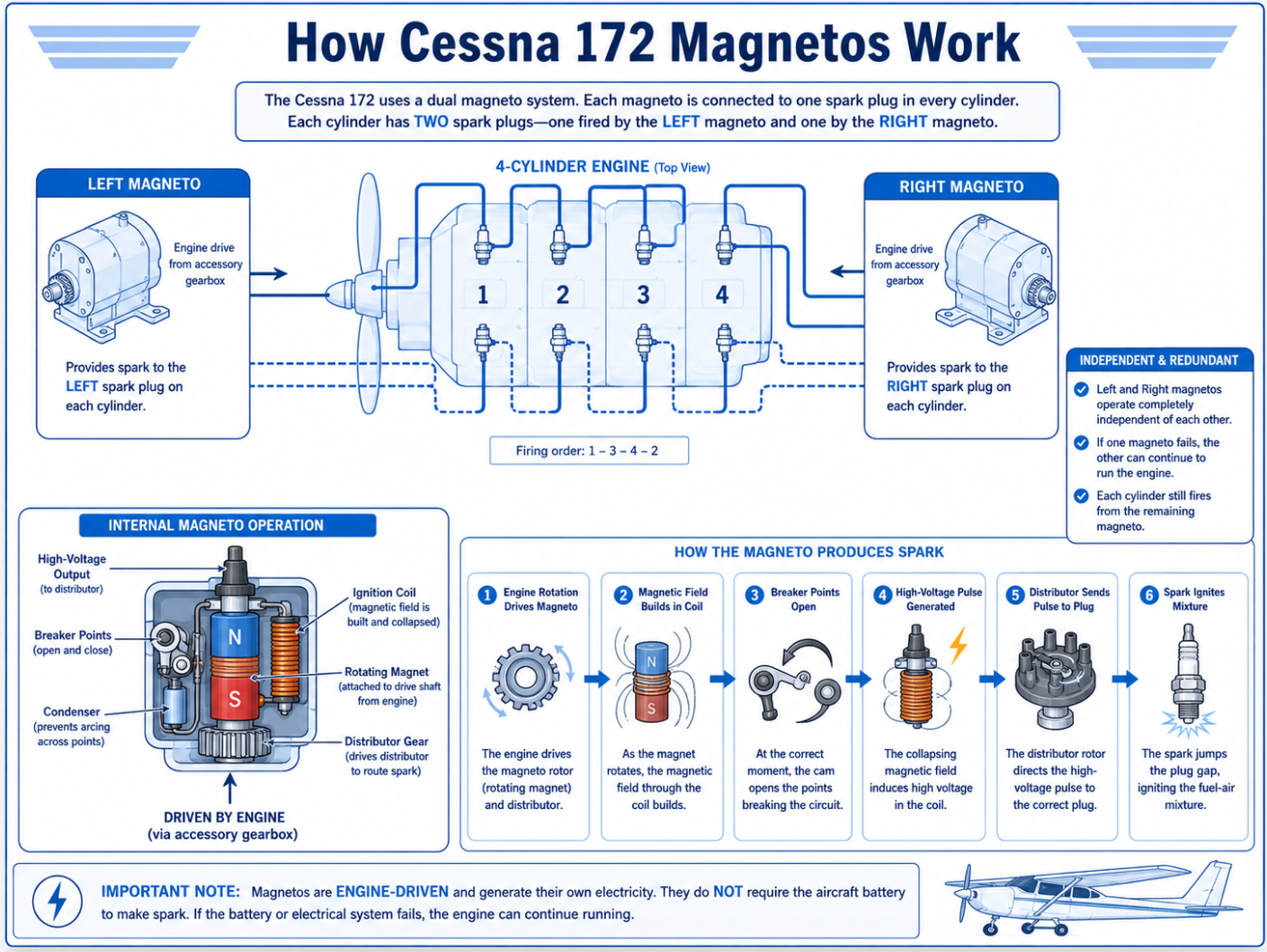
The produced voltage is dependent of the turning speed of the magnet. How faster the engine runs, the more voltage is produced. When starting, the magneto turns slowly and would normally produce a weaker spark. An impulse coupling, often installed on the left magneto, stores spring energy and releases it suddenly. This makes the magneto rotate faster for a moment and retards the spark timing, helping the engine start more smoothly.
A plane which has its contact not set to off runs in standby, and a minor movement in the propellor can result in the engine running. This is called hot prop. Always set the contact to OFF and the mixture to Idle cut-off when parking a plane.
Start vibration
An alternative solution to the impulse coupling is an electrical starting vibrator or shower-of-sparks system. This uses battery power to provide a series of sparks during engine start, but it depends on sufficient battery power.
Ignition moment
The ignition must happen on the right moment to be effective. If the fuel/air mixture is not ignited at the right moment, this will work against you instead of helping you further.
- Pre ignition: This is when the mixture is ignited before the normal spark timing, often by a hot spot in the cylinder. In Dutch called: “Voorontsteking.”
- Detonation: This is abnormal combustion where part of the mixture explodes instead of burning smoothly after the normal spark. This causes very high pressures and temperatures and can lead to serious engine damage.
Some causes of detonation are:
- High engine temperature and too less cooling
- Too lean mixture
- Hot spots in the engine, like a hot spark plug
- Fuel with too low knock resistance or too low octane number
- Pre ignition
Spark plug contamination
A spark plug that has the right working temperature, will clean itself and will be free of carbon or lead. With running stationary for a long time, the optimal temperature will not be reached and can result in the engine running too rough. This is the reason we set the engine for around 1000 rpm during taxi and stationary, which is higher than the complete idle RPM, which is around 600-650RPM.
Diesel engines and ignition
Diesel engines doesn’t have spark plugs. Diesel engines will suck air and compress this. At the end of the compression stage the diesel will be injected into the cylinder, causing it to ignite due to the high pressure and temperature. Mostly similar to gasoline-driven engines but doesn’t have spark plugs.
Ignition switch
General aviation planes have a ignition switch where we control the ignition system with. This mostly have 5 different modes:
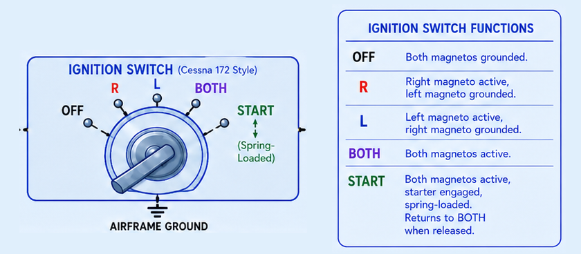
- OFF : Here the magnets are connected to the ground of the plane and disconnected from any source of power. Actually connecting the primary coil of the magneto’s to the ground (-). No sparks will be produced in this setting, during normal situations
- R : Only the right magneto works in this setting
- L : Only the left magneto works in this setting
- Both : Both magnetos are working in this setting
- Start : The starting engine is powered in this setting and only the left magneto as impulse
During the before take-off checklist, we test the magneto’s on working and stability. If one of the two is not working properly, we will confronted with this at this moment. If the engine is running on one of the two magnetos, we should get a ~10% RPM drop. If one magneto is defective, selecting that magneto can cause a large RPM drop or the engine may stop. If there is no RPM drop at all when selecting one magneto, this can indicate a grounding problem, meaning one magneto may still be live when it should be switched off.
A magneto can also be defective due to a grounding problem. During the run up, we will not see an RPM drop on one of the two separate settings. This can make the plane dangerous, and we may not park this plane without a good indication mark, as the magneto’s will be still powered. Rotating the prop even a bit can result in a possible engine start which a person will not survive. This will be minimized by disabling the engine using the mixture to idle, where no fuel is left in the cylinders and nothing to burn. This is the standard accepted way to turn off an airplanes’ engine.
Engine cooling (5)
When burning fuel, a huge amount of heat is produced. As this will increase at higher RPMs and higher throttle settings, the engine needs to be cooled. Proper engine cooling extends the lifetime of an engine. At the best working temperature, the engine runs optimally which we want. We then get the most out of the engine. Other cons of high engine temperatures are thin or burnt oil, defective pistons, spark plugs and such.
In general aviation aircraft, these types of engine cooling is being used:
- Air cooling
- Liquid cooling
Most aircraft use air cooling or a combination of both. Liquid cooling is often used for cylinder heads and with diesel engines.
Apart from the cooling system, excess warmth is also dispatched through oil and oil coolers. A richer mixture can help cool the engine because some excess fuel evaporates and absorbs heat. This is mainly relevant at high power settings, but mixture use must always follow the POH.
Air cooling
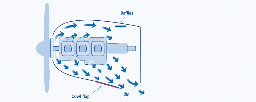
The cooling with air is very easy on airplanes. As air will flow through the openings at the front when flying this already has a major impact. The propellor also blows some air into the inlets at the front. Inside, most parts are equipped with big metal parts which pickup most of this air to cool and conduct the heat out. Most parts have cooling fins, making the contact-surface bigger and better cooling. Inside the engine compartment, some baffles (leiplaten) are added to redirect the airflow for optimal cooling.
Optimal cooling of the engine is reached during the cruise phase, as this redirects the most air at the highest speed into the air intakes. During climbs or running stationary the cooling will be worse.
Cowl flaps
Cowl flaps control the airflow through the engine cowling by changing the outlet area. Open cowl flaps increase cooling airflow but also increase drag. These are often used in turbo-compressor engines. These are mostly open during taxi, take-off and climb and closed on cruise. Then re-opened at landing. If a plane has any problems with cooling in cruise, they can be re-opened.
Liquid cooling
An engine can also be cooled with liquid. Liquid can reach places with tubing where air cannot flow through. However, this is another extra reservoir, radiator and pump which can be defective. Liquid cooling is also more stable, and the radiator will only be opened when the cooling liquid reaches around 80-85 degrees celcius. Also the liquid will expand when being warm and contract when its cold, so an expansion reservoir is also installed.
Engine lubrication (6)
An engine needs to be lubricated using oil. The oil has these primary functions:
- Decreasing friction between parts
- Decreasing temperature and wear
- Cooling by conducting due to friction and burning which is called internal cooling
- Transporting small parts of wear and burnt carbon particles
- Securing metal surfaces from corrosion and from burnt fuel
- Closing the gap between cylinder wall and piston
We can use oil in two separate ways to get oil at the right places where engines can use both simultaneously:
- Pressure lubrication: Primary way, uses pressure built up by a pump to flow the oil around the circuit, reaching the crank shaft, bearings and camshaft.
- Splash lubrication: Uses splashing to cool and lubricate the bottom of the pistons and cylinders and bottom of the crank shaft
Oil circulation systems
In airplane engines, we can use two different oil circulation systems:
- Wet sump : In a wet sump system, oil is stored in the oil cump (carterpan), installed at the bottom side of the engine. The oil pump will pump this oil from the sump to the oil filter and then through the systems. From the engine, every droplet of oil that leaks is redirected back to this sump. This system is cheap and light and therefore used in much smaller airplanes
- Dry sump : In a dry sump system, oil is stored in a separate tank. The engine has a small carter to catch oil which drops back from the engine after doing its job. A separate scavenge pump will pump the oil which reached the carter to the oil reservoir. A dry sump system needs therefore two pumps, one for the system and one to pump oil back to the reservoir. This system is mostly used in aerobatic planes, where the engine is inverted so you can fly at inverted positions without an engine that turns off.
Oil cooling
To cool the oil and regulate the temperature of the oil we have a oil cooling system, equipped after the oil pump, before the oil is pumped into the engine. This cooler is a thermostatic temperature regulator which is cooled by the cooling air which flows in the engine compartment. This also works with a bypass system, redirecting directly or via the cooling compartment. If the oil pressure is high, this will also open to always have oil in the engine.
The oil filter is a paper filter in a metal case, around the size of a can of soda and is replaced according to the aircraft or engine maintenance schedule. In many training aircraft this can be around 50 flight hours, but the exact interval must be checked in the maintenance manual.
Engine oil types
Oil consists of hydrocarbons and needs additives to lubricate the engine in a broad working temperature range. A cold engine needs to have the same lubrication as a warm engine. Oil has the following properties:
- Viscocity : The viscocity of the oil states how syrupy the oil is. The higher the number, the thicker, and the more resistance of flowing, also dependent of the temperature of the oil
In plane engines, we use both single grade and multigrade oil types. Single grade has big difference in temperature ranges and multigrade is “graded” for multiple temperature ranges. In warmer conditions, an oil grade suitable for higher operating temperatures is often required. In colder conditions, thinner or multigrade oil can help during cold starts.
The indication is:
- Single grade oil : oil 80 or 100
- Multi grade oil : 15W50
Multigrade has the gradation in the name. During cold operations, the first number with the W describes the cold-temperature viscosity behaviour. At normal engine operating temperature, the second number describes the viscosity behaviour. In this number, the W stands for “Winter”, so Viscocity 15 during Winter (cold start) and 50 during engine operating temperature.
Oil pressure
In the oil system, the oil pressure is regulated by the oil pump which is directly driven by the engine. The oil pump delivers pressure at a very low temperature. To prevent the pressure exceeds the limits during high RPM situations, the engine contains a pressure relief valve. Via the pressure relief valve the oil will be pumped back to the carter. This flap will open at a certain pressure and stabilizes the oil pressure.
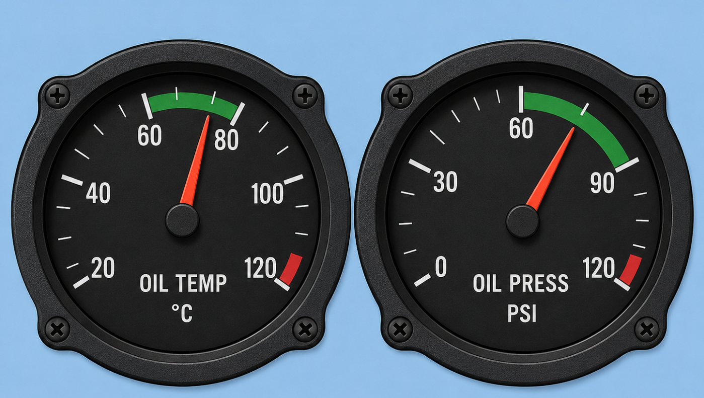
The most important indicator of the oil system is the oil pressure meter. A minimum pressure is needed to take care of having enough oil in the engine and enough cooling and lubrication.
- Low oil pressures: Lead to bigger wear, high temperatures and in worst case engine failure
- High oil pressures: Lead to leakage, damaged oil filter or damaged oil cooler
The normal and allowed ranges and limits are described in the POH. On the indicator, we get a good view of what is normal, too high or too low.
Too low and too high oil pressure can have similar causes, so let’s sum them up in a table:
| Cause | Too low pressure | Too high pressure |
|---|---|---|
| Wrong oil | Too thin | Too thick |
| Too low oil value | Yes | No |
| Oil temperature | Too high | Too low |
| Blockage in the oil system | Yes | Yes |
| Defective oil pump | Yes | Yes |
| Defective indicator | Yes | Yes |
| Defective oil pressure relief valve | Yes | Yes |
A high oil pressure can happen if the engine is just started and cold. The oil is too thick and will be pumped hardly into the engine. When the engine has warmed up the viscocity will lower and the oil pressure will be within normal operating ranges. An engine takes around 10-20 minutes to fully warm up every component.
Oil temperature
Next to the oil pressure, the second most important indicator of the engine health is the temperature. The temperature will decide the viscocity and the lubricating properties of the oil. High engine temperatures can be caused by:
- Too much heat production in the engine, high environmental temperature
- Flying at high RPM too long
- Lean mixture
- Too less cooling in the engine, possibly during climb
- Too low engine oil-value
- Defective or dirty oil cooler
- Defective indicator
The oil temperature is dependent of the operating temperature in the engine. If this temperature is too high, then we can take some steps to try and resolve this high temperature by picking less RPM, flying faster for more and better airflow, riching the mixture or to open the cowl flaps.
High oil temperatures often happen with low pressure. By the high pressure, the pressure drops as the oil gets thinner. If the engine cooling is enhanced, the temperature and pressure will be normalized.
Oil usage
Every engine will use oil but the amount of oil is dependent on several factors. The oil usage will be dependent on:
- Type of oil
- Condition of cylinders
- Condition of pistons
- Condition of piston rings
A new engine which doesnt have already lubricated piston rings uses more oil. The same counts for older engines with much wear to the piston rings.
Constant Speed Propellors (7)
Constant Speed Propellors or variable pitch propellors are propellors where the angle of the propellor blades can be adjusted based on the phase of flight. Planes with this feature are equipped with a blue Prop RPM handle in the cockpit, next to the black throttle and red mixture. Pro’s of planes with this feature is that they are much more efficient, generating more thrust with less engine RPM. With the black handle, we control throttle/manifold pressure, and with the blue handle we select the propellor RPM. The governor then changes the blade angle to maintain the selected RPM within the operating limits.
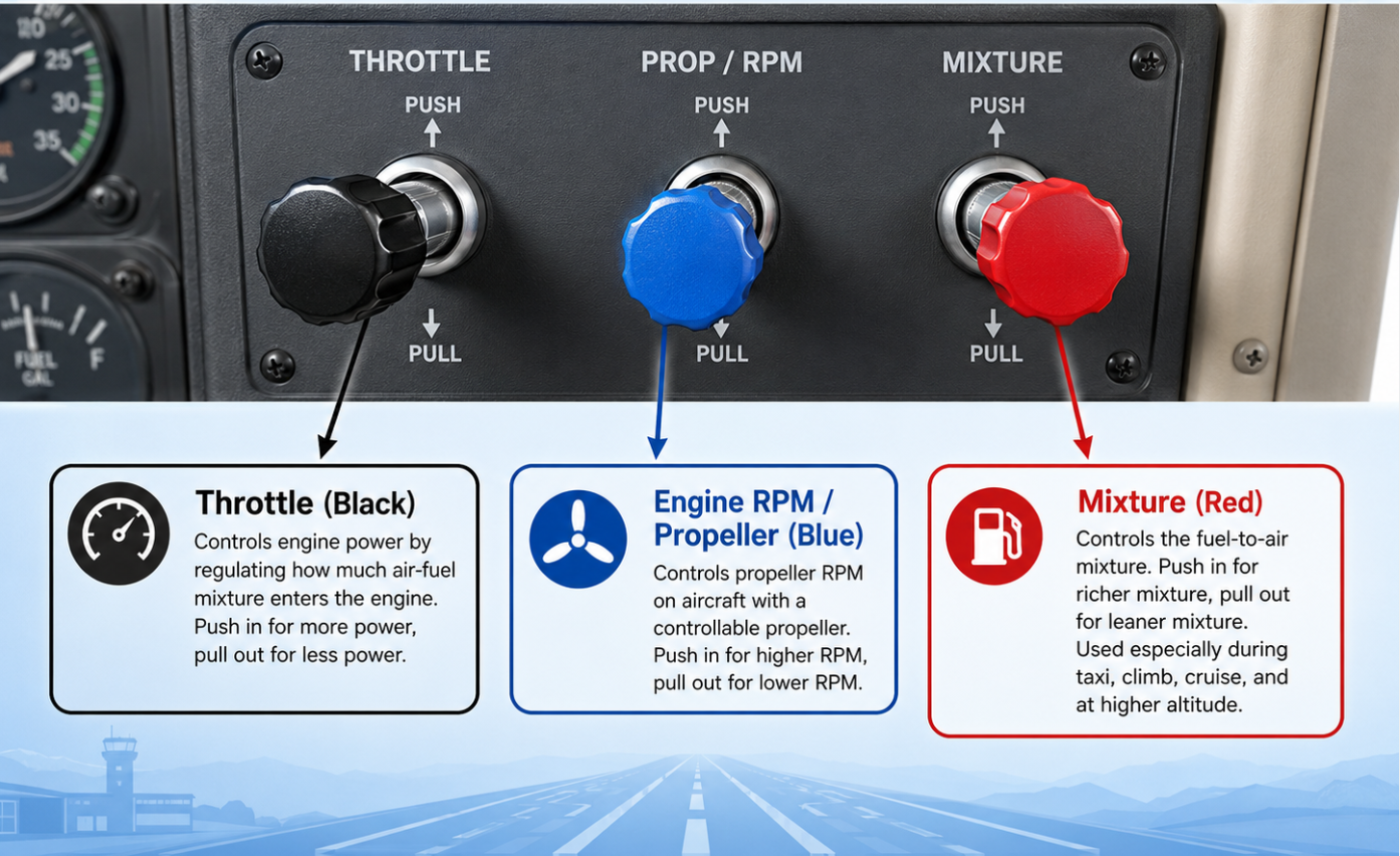
Planes equipped with constant speed propellors are also equipped with a governor. This is a part in the plane that actually sets the correct propellor blade based on the handle setting.
- When taking off and climbing: blades are set to full fine ( High RPM )
- When cruising : blades are set to coarse blade angle ( Low RPM )
As the propellor governor tries to maintain the selected RPM, the angle of attack and drag can reduce when in horizontal flight as we go at a faster airspeed. This makes the plane setting a more coarse blade angle to increase this, making the engine run on lower RPMs than with fixed pitch propellors and having more control + efficient use of engine power.
Most blade-change systems are hydraulic, but some are also powered electrically. Hydraulic systems make use of the oil pressure to control the mechanism, so this also uses engine oil.
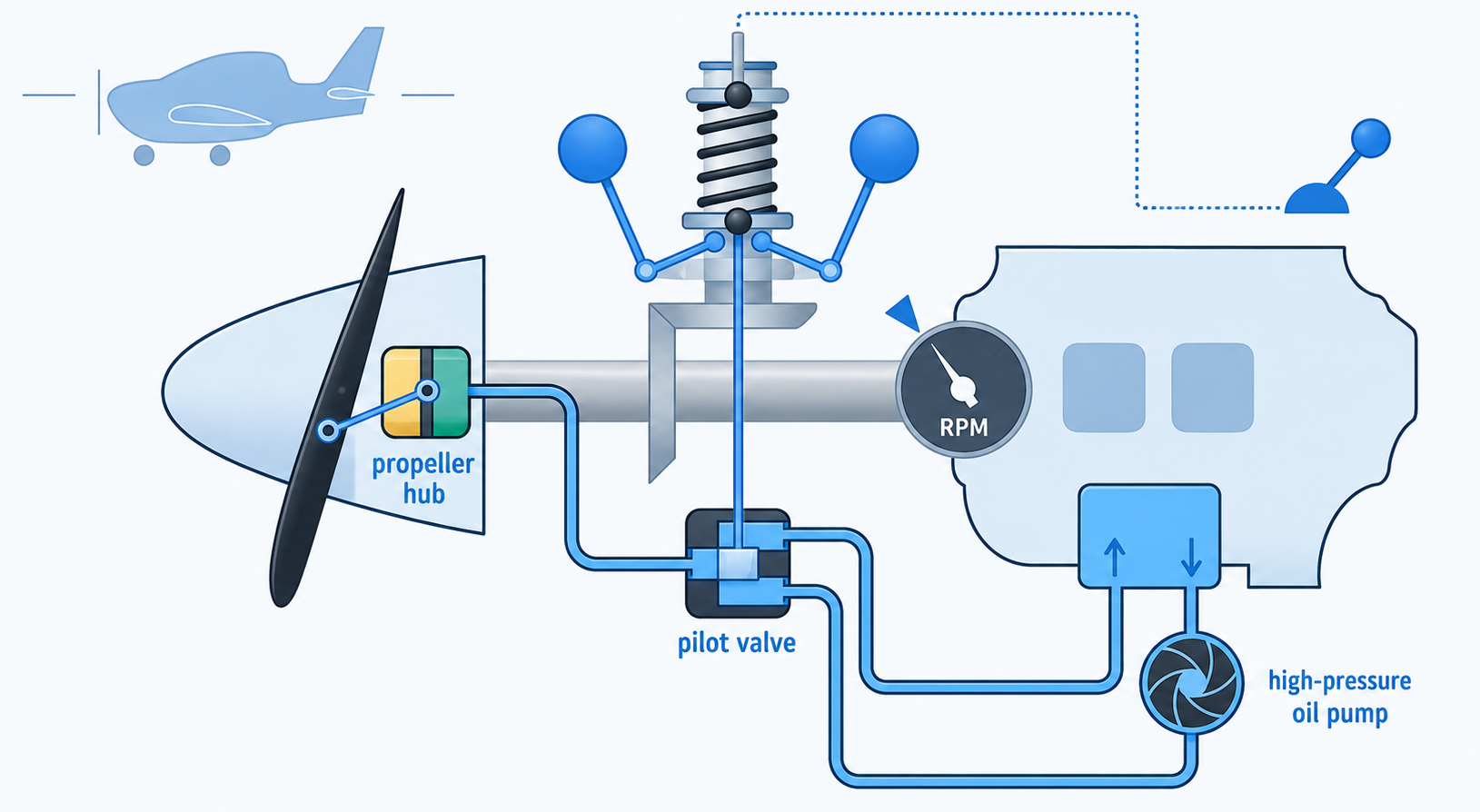
How this system works:
- When setting the handle to Low RPM which is fully backward, the spring on the governor (the vertical pipe and part of the constant speed unit) will push on the fly weights which are those two balloons, making them fly outwards. They rotate at the crank shaft speed as a gear connects the governor to this crank shaft
- The fly weights are engine RPM sensitive, making them fly outwards due to high RPM and fly inwards at low RPM due to centrifugal force
- The fly weights are connected to the pilot valve, which is a valve that can complete the oil circuit to the propellor, in Low RPM settings this valve will open, at High RPM the valve will close
- The propellor hub is hydraulically powered by the high pressure oil pump pushing the blade to a bigger angle.
Overloading the engine
When a high manifold pressure is combined with a low engine RPM the engine can fill up the cylinders too much, causing extreme pressure and temperature in the ignition space and can overload the pistons and crank shaft. This also increases the chance of detonation. Refer to the POH of the plane for recommended setting combinations. A simple comparison is driving a car in a high gear at low speed and pressing the accelerator hard. The engine has to work very hard at low revs.
- To increase power: increase RPM first, then increase manifold pressure
- To reduce power: reduce manifold pressure first, then reduce RPM
Pre-flight check
During the pre-flight check, we will check the governor operation. This can be done when the engine is running and when it is in normal operation temperature. We will set the handle over the full range for a few times and check if the RPM changes value. Doing this multiple times helps warm engine oil reach the propellor governor system and confirms that the RPM changes as expected.
Single acting variable pitch propellor
Smaller planes are often equipped with single acting variable pitch propellors, where the blade angle is controlled one-way with oil pressure. The oil pressure ensures a coarse blade angle where centrifugal forces will ensure a fine pitch angle.
Loss of oil pressure
As we already discussed, when powered hydraulically, the system uses the engine oil to function. The pitch of the blades is mechanically limited to help us in failures. In many single-engine, non-feathering constant-speed propellors, loss of oil pressure drives the blades toward fine pitch/high RPM, making it behave more like a fixed pitch propellor and keeping us able to land safely. This also needs a limited airspeed and limited engine RPM setting as the engine RPM can now be exceeded by the low propellor drag.
Leaning the engine in a Constant Speed Propellor plane
In an aircraft with a constant-speed propeller, engine RPM is controlled by the propeller governor, so RPM is not a reliable guide for leaning the mixture. Instead, the Exhaust Gas Temperature (EGT) indicator shows how hot the combustion is, which helps you find the correct fuel/air mixture. As you lean the mixture, EGT rises until it reaches peak EGT, then starts to fall. Pilots use this indication to set the mixture either near peak EGT or slightly rich/lean of peak, depending on the engine manual and operating conditions. The main reason is to get efficient combustion while avoiding an incorrect mixture setting.
Climbing with a Constant Speed Propellor plane
When climbing, and we don’t change anything to the configuration of the throttle, RPM and Mixture, the Manifold Pressure (MAP) will decrease slowly due to the lower outside air pressure.
Engine Instruments (8)
The engine is of course one of the most important systems in our aircraft. Without the engine we were not able to produce enough thrust to produce lift, and being able to fly. As we have several instruments in the cockpit that tells something about the current state of the engine at any time, we will dive into the properties of each indicator and system.
Let’s take a look at the types of engine instruments we have in our cockpit:
- Pressure-indicators
- Temperature indicators
- Revolutions per minute (RPM) indicator
- Fuel indicators
We will dive deeper into the various indication systems and what we can expect from our plane.
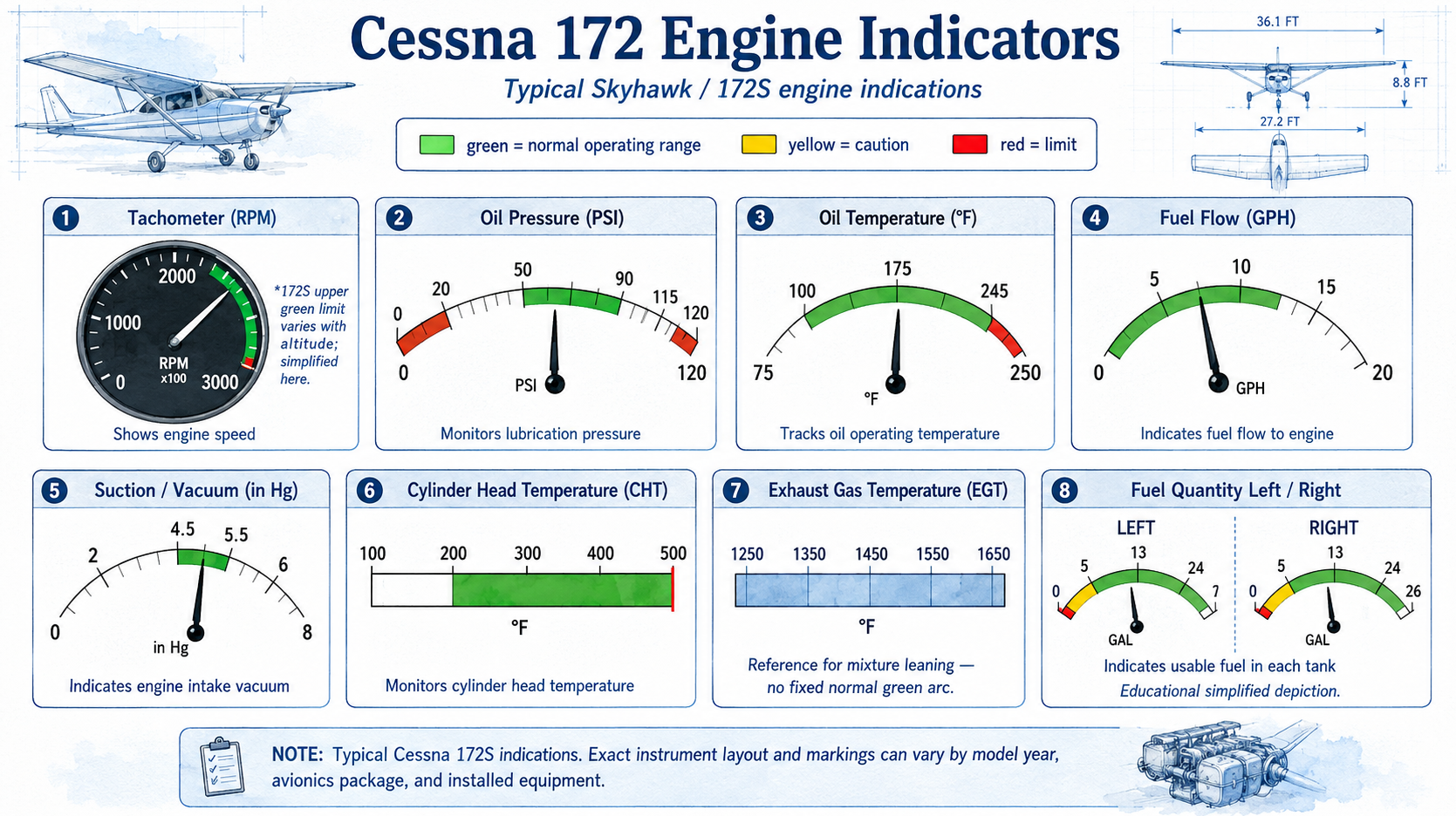
Color markings
All of the indicators in an aircraft are marked with colors to tells us easily if units are within limits or not. Here we can take these into account:
- Green area: Normal operating range, everything healthy
- Yellow area : Operating area with possible precaution but indicators can reach this in situations like take-off
- Red line : Minimal and maximum value for safe use
- Red area : Non-normal area and will indicate possible failures if not reacting to them
Pressure indicators
The engine indicators measuring and showing pressure are:
- Oil pressure : this shows the pressure in PSI and the rate of circulation
- Fuel pressure
- Manifold Pressure: This shows the absolute pressure in the intake manifold after the throttle valve. It is expressed in inches of mercury (inHg) and is used together with RPM to manage power in constant-speed propellor aircraft.
- Static and Dynamic pressure
- Hydraulic pressure
We can indicate pressure primairily with the Pascal unit. One pascal is equal to one Newton per square meter (1 N/m²). In most cases, some older or American units are used in aircrafts:
| Unit | Pascal (1 hPa = 100 Pa) | |
|---|---|---|
| Bar | 1 millibar | 1 hPa |
| Inches of mercury | 1 inHg | 34 hPa |
| Pound-force per square inch | 1 psi | 69 hPa |
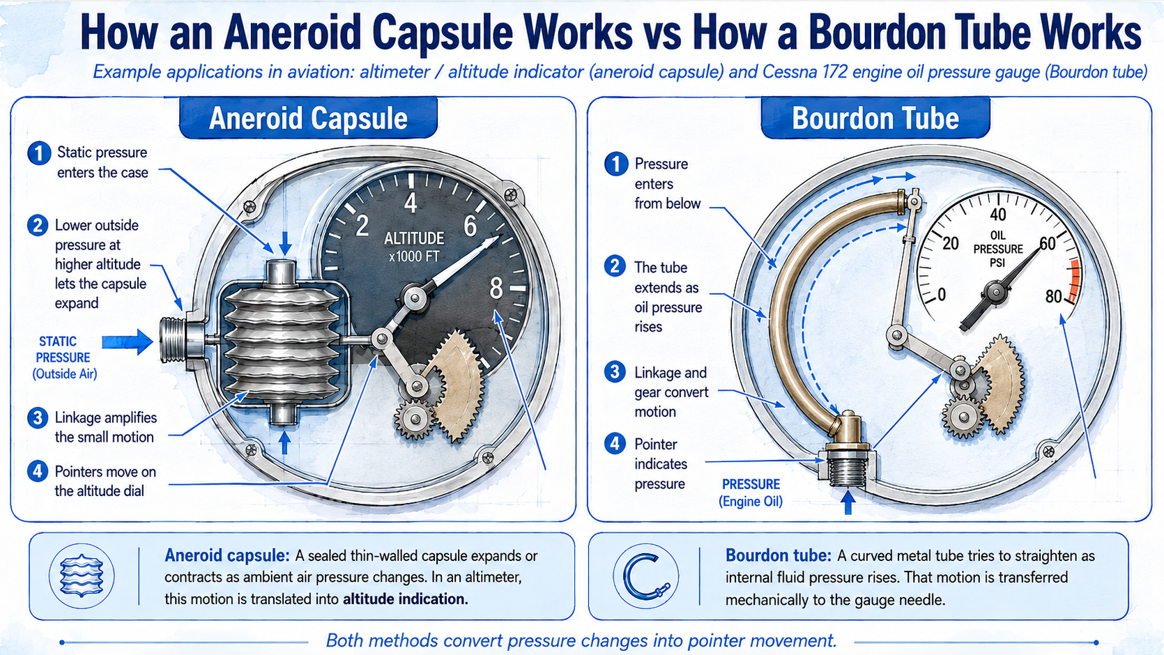
Pressure is mostly measured by flexible metal boxes or pipes. We have two types which are mostly used:
- Aneroid: This is a method where a diaphragm is used. This diaphragm is placed in a box with the pressure connected to the static pressure system with a determined amount of pressure inside the diaphragm. This diaphragm expands and contrapts based on the static pressure in the box, giving an indication by a grear connected indicator needle.
- Bourdon-pipe: A bourdon pipe is a mechanical solution of measuring high amounts of pressure. This is a flexible pipe which will stretch when the pressure inside increases. This stretching movement is then transferred using a gear to the indicator needle, showing the actual state of the pipe behind.
Temperature indicators
Temperature in aviation is often measured in these three units:
- Celcius (C) : This is the primary method around the world to measure temperature, which has a simple and logical scale:
- 0 degrees: freezing
- 100 degrees: cooking
- Kelvin (K) : This is the temperature scale where 0 K is absolute zero, equal to -273,15 degrees Celsius.
- Kelvin = Celsius + 273,15
- Fahrenheit (F) : This is an American scale, where 0 degrees celcius is 32 degrees Fahrenheit
- Fahrenheit = Celcius × 1,8 + 32
We get some indications about temperatures in our aircraft, telling us different things:
- Cylinder Head Temperature (CHT): Measuring the temperature of the cylinder head metal. This is important because the cylinder head is one of the hottest and most stressed parts of an air-cooled piston engine and too hit CHT can lead to a rough running engine. High temperatures can be resolved by
- More rich mixture
- Decrease of engine RPM
- Enhancing cooling, open cowl flaps or fly at a higher speed
- Exhaust Gas Temperature (EGT): EGT shows the temperature of the exhaust gases leaving the cylinder. It helps the pilot monitor combustion and is especially useful when leaning the mixture. During leaning, EGT normally rises to a peak and then decreases if the mixture is leaned further. Pilots use EGT, together with the aircraft’s POH and engine limitations, to set the correct mixture
- Oil Temperature: The temperature of the engine oil and so the mean engine temperature, giving us indications of possible overheating
- Coolant Temperature: The temperature of the coolant fluid, giving us indications of possible overheating
- Outside air temperature: This indicator measures the temperature outside of the aircraft, enables us to make TAS calculations or assess risk of ice deposits
Revolutions per minute (RPM) indicator
We have one RPM indicator per engine. In a single-engine aircraft we monitor one RPM indicator; in a multi-engine aircraft each engine has its own RPM indication.
RPM indicators show the amount of rotations the propellor makes in a minute. In planes where the propellor is mounted directly on the crank shaft, we also get the RPM of the crank shaft with this indication. With fixed-pitch propellor planes, this means engine RPM equals propellor RPM. More RPM is more power (thrust).
Some engines like Rotax have a gearbox between the crank shaft and the propellor which allows the propellor to rotate at a lower RPM than the engine. Depending on the installation, the cockpit RPM indication may show engine RPM rather than actual propellor RPM.
Propellor RPMs are often limited to around 2700 RPM in many light aircraft engines. The exact limit depends on propellor diameter, tip speed, noise, efficiency and structural limits.
RPM indicators are very often mechanically powered. A flexible cable is connected to the engine on one end. The other end is connected to the RPM indicator in the cockpit. This other end has a magnet connected to it which rotates in a copper tube. This will produce eddy currents, resulting in the copper tube rotating in the same direction. The rotation of this tube is then somewhat limited by a spiral spring.
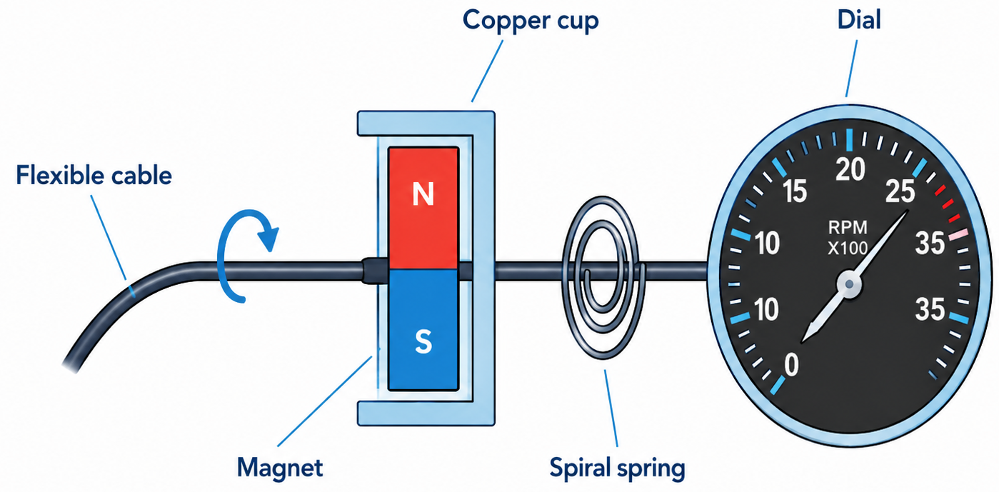
Eddy currents are electrical currents induced in a conducting material when it is exposed to a changing magnetic field, for example by a rotating magnet.
Some planes are equipped with a torque indicator as indicator for the amount of engine power. A torque meter is often used when the crank shaft and propellor are separated by a gearbox and is determined by performing oil pressure measurements in the gearbox.
- Torque (Nm) = force (N) × arm (M)
- Power (Watt) = torque (Nm) × angular velocity (rad/s)
- If using revolutions per second: Power = torque × 2π × revolutions per second
_Nm = Newtonmeter, unit of rotation power where we multiply the amount of newton against the amount of meters (_10 N × 0,5 m = 5 Nm)
Some planes also show a percentage of the maximum power or the engine power rating (EPR), but this is mostly used on Jet airliners.
Fuel indicators
The engine indicators measuring and showing properties about the fuel are:
- Fuel pressure: This shows the pressure of the fuel in the tubes to the carburetor. This is required when the plane has a fuel pump as primary circulation force, where a low fuel pressure can indicate a low tank or a defective fuel pump
- Fuel quantity indicators: This logically shows how much fuel there is in a certain tank using a floating object, connected to a metal arm which is electronically powered. This is by far the most inaccurate instrument in a plane, so always do a physical inspection with a dipstick. Its also unaware of the attitude of the plane.
- Fuel temperature: This indicates the temperature of our fuel and is mostly equipped in diesel aircraft. Diesel can partly freeze (waxcrystals) when under -20 degrees celcuis
- Fuel flow: This measures how much fuel travels through the fuel injection system every hour. This can be used to determine our fuel calculations, and is often measured at the injector or a specfic measurement-wheel in the tubes
To calculate different units:
- 1 pound (lb) = 0,4536 kg
- 1 US gallon (USG) = 3,785 liter
- 1 Imperial Gallon = 4,546 liter
- 1 Quart (qt) = 0,95 liter or 0,25 USG
Tip: Use this unit conversion tool: https://flighttools.justinverstijnen.nl/unitcalculator
The electrical system (9)
The electrical system in planes is being used to power the electronic devices and instruments. The electrical system and the engine are connected through several systems, such as:
- Starting engine
- Alternator/generator
- Electrical fuel pump if equipped
- Engine sensors/instruments
- FADEC if equipped
All the primary components of the electrical system are (and fail in case of electrical failures):
- The alternator (dynamo): The propellor to power delivery device and is the primary source of power if the engine runs
- The battery : provides power when the engine is not running
- Busses : One or more electrical busses where power from the alternator or battery is distributed over multiple electrical devices
- Circuit breakers : Each part of the electrical system have a circuit breaker, a poppable weak link of the circuit to prevent overloading and as result damage to devices
- Wires : to connect each part to each other and to deliver power
- Ammeter : This indicator will show the actual power-usage/delivery
- Master switch : To provide the complete electrical system power from the battery and/or alternator. This is mostly a double switch, where we can also select only the battery or only the alternator in case of failures
- Avionics master switch : To provide all navigation and communication devices power from the battery/alternator
All devices which we often use are powered by this electrical circuit:
- Radio’s
- Navigation systems
- Transponder
- Turn coordinator (only electrical primary flight indicator for fallback scenarios)
- Flight displays
- Fuel quantity indicators
- Inside lights
- Outside lights (Beacon, Strobe, Nav, Taxi and Landing lights)
- Pitot heat
- Clock
- Hobbsmeter (hour-counter on the RPM indicator, just like KM’s in a older carr)
- Electrical trim
- Starting engine
- FADEC
- Flaps
Voltage and current
Some definitions we must know when talking about the electrical system:
- Current : Current is the flow of electrical charge, indicated in Ampere (A). It measures how much charge flows through a circuit per second.
- Voltage : Voltage is the electrical potential difference, indicated in Volts (V). It can be compared with electrical pressure that pushes current through a circuit.
Types of power
We can have two different types of power, namely:
- Direct current (DC) : In DC, the current flows in one direction. Conventional current is described as flowing from positive (+) to negative (-), while electron flow is from negative (-) to positive (+).
- Alternating current (AC) : Here the electrons will switch direction periodically, which is indicated in Hertz. 400Hz means 400 switches of direction per second. In airliners, the alternating current flow hertz is 400Hz, but at your power outlet at home, 50Hz or 60Hz is being used, depending on your country.
We use both of these type of power, mostly depending on the king of application. A battery for example always delivers DC power and an alternator can deliver both. However, alternators that deliver AC power are much cheaper so we can convert that power to DC. General Aviation aircraft mostly have a DC power system of 14 or 28 volts.
Electrical circuits
An electrical circuit conststs of a source of power, like a battery or alternator and one or more users of power, connected by copper wires. Power can only flow if the circuit is closed.
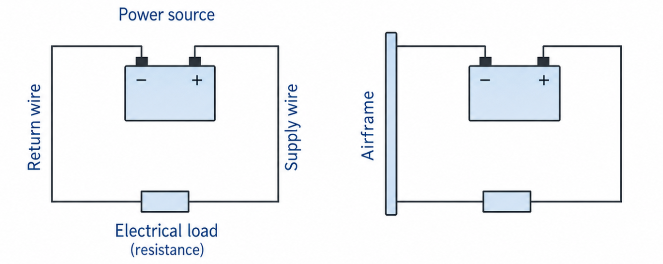
In planes and cars, the negative pole of the battery is often connected to the frame, functioning as common earth. This saves a lot of wire as only the positive pole needs to be connected from the battery to the device and the negative can be picked elsewhere.
The alternator
The alternator is the primary source of power in an aircraft while the engine is running. The alternator is powered by the engine using the V-string. The battery is used to charge and to power the devices when the engine is not running and to provide power to the starting engine to start the engine and make the alternator work.
I use the word Dynamo here a lot, as this is the Dutch translation and because an generator and alternator are different things. I mean with a dynamo a device that produces power.
- Generator: DC dynamo
- Alternator: AC dynamo
A dynamo works by a rotating magnet between static magnets. This causes the rotating magnet to spin at a very high speed, providing power using magnetic induction in a coil.
DC generator
A DC generator is a dynamo that generates DC power. This works with a stator and rotor, where the stator is a permanent magnet with a rotating coil with a lot of wires. One of the wires is shown in the diagram below:
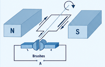
The rotor is connected via the V-string with the engine causing it to rotate as the engine runs. This produces an induction-power which then is picked up at A.
The downsides of this construction are:
- Brushes are maintenance-intensive
- Low RPM is low power generation
- Expensive
Most planes are because of these reasons equipped with an alternator (a AC dynamo).
AC alternator
An AC alternator works similar to the DC generator, by using magnetic induction. But the construction is somewhat different, so AC power is being produced instead of DC power. The construction is completely reversed, the magnet rotates instead of the coil. The magnet is then very often a electromagnet. The power is then picked from the stator which doesn’t rotate, making this solution more robust and less prone for failures.
Because the alternator uses an electromagnet, a small amount of power is needed to power the device. Without power no magnet can rotate. This power is called excitation current.
After the AC alternator, a rectifier unit is placed to convert these alternating current into direct current, usabe by the rest of the plane and charging the battery.
Alternator control unit
The power the alternator is producing is dependent on the RPM of the engine. To prevent damage or outages due to peaks and lows, the electrical system has a alternator control unit which is basically a voltage regulator. A device which keeps the power steady within the correct range. In many light aircraft this is around 14 volts for a 12V battery system, or around 28 volts for a 24V battery system.
The battery
The battery has the following primary functions:
- Delivering power when the engine is off
- Delivering excitation current to the alternator
- Delivering power to the starter engine
- Delivering power if alternator fails (back-up power)
Power in a battery is produced by a chemical reaction. There are different types of batteries which are indicated:
- Nickle-cadnium (NiCd): Lighter with the same capacity and better resistant to low temperatures
- Lithium
Sometimes we have multiple batteries to have back-up batteries or a separate excitation battery.
In most planes a lead-acid battery is used, just like in cars. This contains plates of lead submerged in sulfuric acid. This reaction between those two materials produces power, which is reversable. This means we can charge and discharge the battery, or pick power from the battery or charge it back. The battery is placed in a battery box which contains a drain for air ventilation.
Voltage and battery capacity
Batteries always deliver 12 volts or 24 volts. Because the battery must be charged by the dynamo, the voltage of the battery is always lower than the device that charges it.
The capacity of a battery is indicated as ampere-hours (Ah). A battery with a capacity of 50Ah can provide 50 Amps over 1 hour. When you halve the amps, the duration doubles (25 amps for 2 hours, 12,5 amps for 4 hours etc.)
The battery has a specific rating for this Ampere-hour, but this is the theoretical amount. The actual amount is often lower where these conditions lower the capacity:
- Age
- Temperature (cold = less Ah)
Ampere meter
The Ampere meter is a indication in the cockpit which shows the condition of the electrical system. This measures the amount of amps flowing through the wires. We know two different variants of this indicator:
- Zero-centered : This type is often in Cessna and Cirrus planes. This measures the power from and to the battery. In the center we have the 0, and on the left -30 amps and on the left +30 amps. This must be slightly to the right to be in a healthy condition, the battery is slightly charged and the whole electrical system is powered.
- Location: Between battery and bus
- Load meter: This type is the total amount of power in the electrical system. The lowest amount is 0 and the highest amount is 60. When less devices are turned on, the meter shows a low value and with much devices the meter goes up.
- Location: Between alternator and bus
Busses
A bus is a distribution strip, which basically is a static collection of power outlets where all devices get their power from. From the bus the power goes to the circuit breakers and then to the actual devices.
Mostly we have these busses:
- Main bus
- Avionics bus
- Essential bus
- Non essential bus
Circuit breakers and fuses
Fuses are weak links in the circuit which have the goal to break the circuit if a high power is detected. We have two types of these fuses:
- Smelting fuses (right): Smelting fuses have a thin wire which can only withstand the rated power. If more power is connected, the wire will smelt breaking the link. The fuse then needs to be replaced before working again.
- Cirbuit breakers (left): Circuit breakers do the same as smelt fuces but pop if a high power is detected. We can easily re-pop them back into position to make the connection again. These are often called automatic fuses
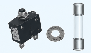
Circuit breakers have a contact with a multi-metal strip. If the power (amps) will exceed the rated limit, the metal will warm up, bending the metal and causing the circuit to break. Circuit breakers that pop must first be cooled down to connect them again. If a circuit breaker pops during flight, EASA recommends to let it disabled when its not needed for a safe resumation of the flight. For example, we can land without flaps or lights or even radio. Altough it would be nice to have them.
Relay
A relay is a electromagnetic switch. An example is a starting relay. To power the starting engine, a huge amount of power/current is needed. Turning the key to START causes a small power to the starting relay, powering an electromagnet which results in a closing of the ignition and causing the starting engine to rotate.
Electrical system disruptions
In the electrical system, two types of disruptions or failures can occur:
- Disruptions where the alternator does not provide power
- Short circuit where something in the system causes a short circuit with possible fire, smoke or electrical smell. This can also lead to a circuit breaker/fuse failure
The general guidelines and sympthoms for both types of disruptions are:
- Low ammeter indication -> alternator error
- Low voltage annuciator -> alternator error
- Electrical smoke -> short circuit
- Ozone-smell -> short circuit
In a case of a alternator error its recommended to land the plane at the nearest airfield as an alternator error will cause the plane to pick power from the battery. The remaining time depends on battery condition, battery capacity and electrical load. Power down unnessesary devices where possible.
The alternator can sometimes be reset by switching the master switch to off and back on.
Pitot-static instruments (10)
The pitot-static system is a system with three indicators from the cockpit connected:
- Speed indicator
- Altitude indicator
- Vertical Speed indicator
Before looking at the instruments and probes, let’s first take a look at the different airspeeds.
Airspeeds
Airspeed in aviation can be measured in 4 different terms which sound ridiculous but this has their specific reasons.
| Speed | Abbreviation | Definition |
|---|---|---|
| Indicated Airspeed | IAS | The airspeed shown on the airspeed indicator, based on the difference between pitot pressure and static pressure |
| Calibrated Airspeed | CAS | IAS corrected for instrument and position errors |
| True Airspeed | TAS | The actual speed of the aircraft through the surrounding air mass |
| Ground Speed | GS | The speed of the aircraft relative to the ground |
Pitot-static instruments
The Pitot and the static port are 2 openings on a plane which measures a different type of pressure:
- Pitot: Measures dynamic pressure -> Speed
- Static port: Measures static pressure -> Altitude
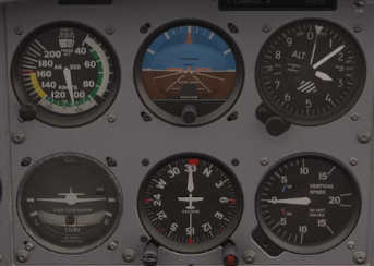
These two components are connected to 3 of the basic 6 instruments we must have in a cockpit:
- Airspeed (Ports/Analogue)
- Artificial horizon (Gyro)
- Altitude (Ports/Analogue)
- Turn coordinator (Gyro/Electrical)
- Heading/Compass (Gyro)
- Vertical speed (Ports/Analogue)
Static port
The static port is an opening (mostly on the left side) that measures the static air pressure while in the air. The pressure it measures is displayed on your altitude indicator.
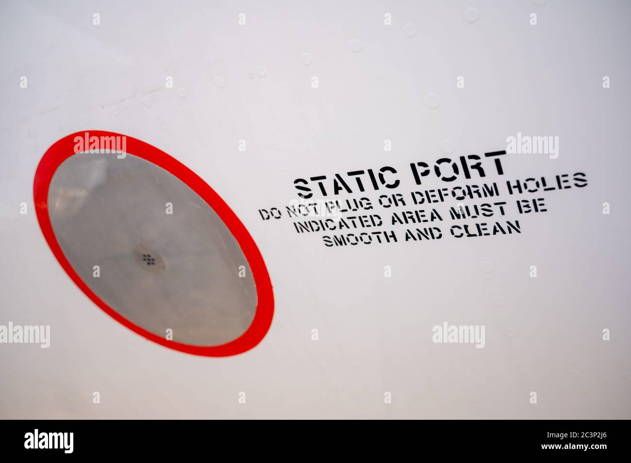
This opening is placed in a position where it is not directly facing the incoming airflow, so it can measure static pressure as accurately as possible. In some planes, this is integrated in the pitot-probe.
When having problems with altitude or vertical speed (like in the winter), we have a second option of static air, the alternate static port/alternate air. This takes air from the cabin. Cabin pressure is often slightly lower than outside static pressure, so the altimeter can indicate higher than the true altitude. The exact correction must be found in the POH.
In some emergency situations, if no alternate static source is available, the POH or training material may describe breaking the VSI glass to provide a static source. This makes the VSI unusable and should only be considered as an emergency measure according to training and procedures.
Position error
The static port cannot always be at the right spot on an airplane. It must measure the static pressure so it must be on the side, but speed, AoA and flaps can influence the airflow around the static port and also the static pressure. This im-perfect placement causes an error in the measurement, called the position error. This has a small influence on the measured altitude, speed and vertical speed. Also some errors caused by manoeuvres can happen. Some planes have multiple static ports to minimize these errors.
This same also applies on the pitot probe, although this only measures dynamic pressure.
Alternate static air/port
Some planes have an extra alternate static port in case the normal port is broken or something. This can be opened in the cockpit, so the air pressure of the cockpit can be used to measure the altitude, speed and vertical speed. The pressure in the cockpit is often somewhat lower than the outside air pressure, so the altitude meter can indicate too much. In the POH you can find a altitude correction table.
Pitot probe
The pitot probe measures total pressure, which is used together with static pressure to determine the aircraft’s airspeed. The airspeed shown to the pilot is called Indicated Airspeed (IAS). It basically converts the amount of air molecules going into the probe and gives this information to the Indicated Airspeed instrument in the cockpit. There it is being corrected for the static pressure to display the correct amount of knots in every situation.
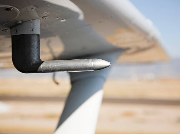
When shutting down the aircraft, a red cover is placed over the pitot probe. This helps prevent insects, dirt, moisture, or ice from blocking the probe, which could cause the airspeed indicator to give incorrect readings or stop working during flight.
Airspeed is measured using both the pitot probe and the static port. The airspeed indicator compares the total pressure from the pitot probe with the static pressure. The difference between these pressures is used to display the aircraft’s airspeed. An increase of the True Airspeed also means more “thrust pressure” (stuwdruk) in the pitot probe as more air passes through it.
Pitot probe errors during blockage
The pitot probe can be blocked by ice, insects, vapor or dumbly enough by forgetting to take the cover off. The exact indication depends on which opening is blocked. If the pitot opening is blocked but the drain hole remains open, the airspeed indicator can drop to zero. If the pitot pressure is trapped, the airspeed indicator can act like an altimeter: too high in a climb and too low in a descent. When this happens, we can expect the following effects:
| Airspeed Indicator | Altitude Indicator | Vertical Speed Indicator | |
|---|---|---|---|
| Pitot probe - climbing | Indicates too high | Stays working normal | Stays working normal |
| Pitot probe - descending | Indicates too low | Stays working normal | Stays working normal |
| Static probe - climbing | Indicates too low | Keeps indicating a specific altitude | Keeps indicating 0 |
| Static probe - descending | Indicates too high | Keeps indicating a specific altitude | Keeps indicating 0 |
| Both - climbing | Keeps indicating the blockage speed | Keeps indicating a specific altitude | Keeps indicating 0 |
| Both - descending | Keeps indicating the blockage speed | Keeps indicating a specific altitude | Keeps indicating 0 |
During take-off, we say the phrase “Airspeed alive” because of this check. If the airspeed is not working before rotation speed, we shouldn’t take-off either as the plane is then categorized as “unsafe to fly”.
Pitot Heat
The pitot has a heating element as this part is sensitive for ice-deposition. To prevent that the ice blocks this instrument, we have a switch in our cockpit called the Pitot heat. This enables a heating device in the pitot probe which prevents ice. This is a part which can take a lot of electrical energy, so do not use it too much when not running the engine. Pitot heat should be used according to the POH/checklist, especially in visible moisture or possible icing conditions.
Airspeed Indicator
Measuring the speed of a plane is based on measuring air pressure differences. Air has a certain pressure which is called the static pressure. As we fly through the air with speeds over 100 km/h, we also have some air flowing into the pitot probe. This is called the total pressure (static + dynamic). As the pitot-static system also knows the static pressure, it can make an easy calculation of what the dynamic pressure is, what then is converted to a readable airspeed indication on the Airspeed indicator in the cockpit.
The calculation that is made:
- Total pressure - static pressure = dynamic pressure
- (P total - P static = P dynamic)
As the pitot probe and the static port are both connected to the airspeed indicator-room in the instrument, here is where the actual calculation is being done. Here is a diaphragm connected to the pitot probe is being filled with the total pressure. In the house where the diaphragm is mounted is connected to the static port.
Speed needs to be corrected for the actual pressure, as dynamic pressure is dependent on the air density. This means that in air with a lower density, without correction, the indicator will be way too low. Airspeed indicators are calibrated on ISA air density, meaning 1,225 kg/m³. This means the indication is only 100% correct in cases where this air density is active.
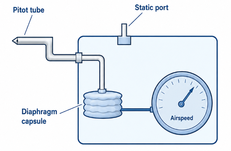
The airspeed indicator has a minor “deviation”, due to minor incorrections in the mechanical parts and differences in air flow. These are called the instrument-errors and we can convert an indicated airspeed to the calibrated airspeed, which differences are very often about 1 to 3 knots. The calibrated airspeed is called the CAS.
So if we want to convert our indicated airspeed to true airspeed, we must go from IAS to CAS and then to TAS. Use the E6B calculator for this.
Airspeed indicator colors
The airspeed indicator has some color codings on the edge, telling you different things very easily:
- Vs0: This is the speed where you get a full stall when extending full flaps
- Vs1: This is the speed where you get a full stall without flaps
- Vfe: This is the maximum speed where flaps may be extended
- Vno: This is the maximum speed where you may fly in normal operations (low winds/laminar air)
- Vne: This is the maximum speed you can fly with the plane before inducing structural damage
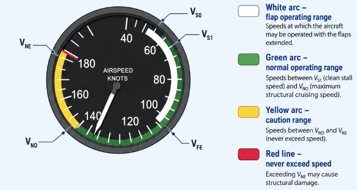
Some planes also can have a Statute mile indicator or even km/h meter instead of knots.
The altimeter
Altitude is expressed in feet or meters in aviation. Most planes and pilots use feet, as this is internationally accepted but some smaller aircraft also use meters.
- 1 ft is 0,3048 meter
- 1 meter is 3,28 feet
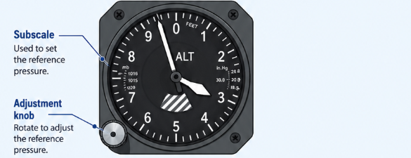
The altitude indicator is basically a pressure-meter. Air pressure decreases as we go higher, and by setting a reference, it knows exactly how far awar we are from that reference point. We have multiple reference points which we can use. The earth’s surface is not perfectly flat, and every piece of land has a different elevation (height above sea level). This is where we use different references, based on the air pressure:
| Q-code | Meaning | When to use | Indication name |
|---|---|---|---|
| QNH | The pressure measured on the ground, and then converted to mean sea level | To measure the altitude above mean sea level | Altitude |
| QFE | The actual pressure on the ground | To measure the altitude above the ground | Height |
| QNE (SAS*) | The ISA pressure altitude, namely 1013 hPa or 29.92 InHg | Above the transition altitude, in the Netherlands 3500 feet | Flight Level |
SAS* means Standard Altimeter Setting, 1013 hPa
In most cases, we use QNH. When QNH is set, the altimeter indicates altitude above mean sea level. On the ground at the aerodrome, it should indicate the aerodrome elevation. When QFE is set, the altimeter indicates height above the selected aerodrome reference and should read approximately zero on that aerodrome. When 1013 hPa is set, the altimeter indicates pressure altitude, used for flight levels above the transition altitude.
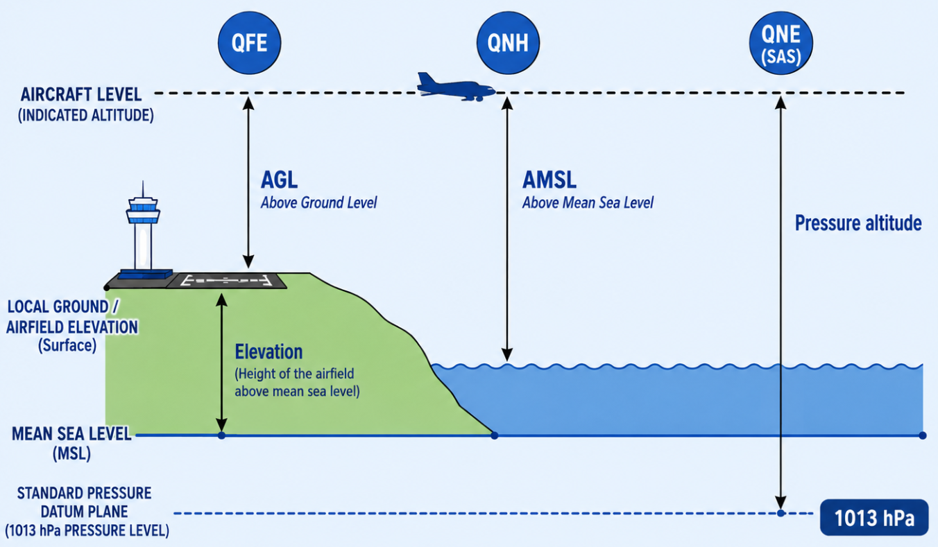
In flight regions we often use a “regional QNH”, which prevents us from 2 problems:
- Different planes having different references, possibly leading to collisions
- The need to set the QNH every several minuts if flying from low to high or high to low pressure areas
How the altimeter works
The altimeter is as said basically a pressure meter (barometer), converting a pressure difference between your reference point and the static pressure measured by the static port to an altitude number in feet. The static port is connected to the instrument-chamber where a diaphragm(s) is placed. This diaphragm(s) has a certain pressure in it and the outside pressure pushes on the diaphragm(s). As you increase in altitude, the static pressure decreases, which causes the diaphragms to expand. This is then mechanically contected to the indicator needles and showing the pilot the altitude from their reference point. The diaphragm is also known as aneroid.
You can set the reference point with the dial in the cockpit.
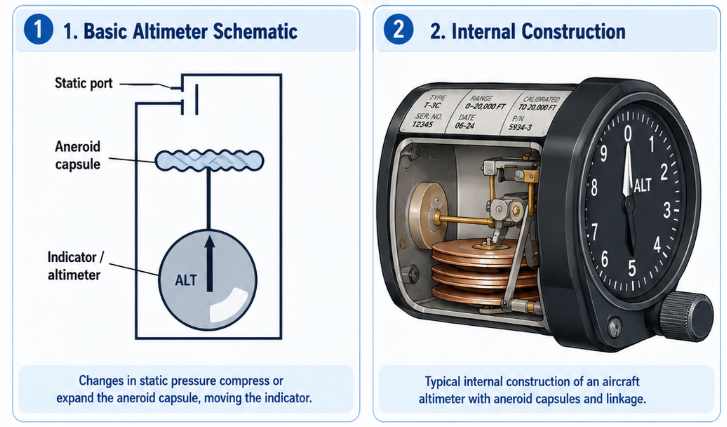
The altitude indicator mostly has 3 indicator needles, and works like a clock:
- Big needle: Showing 100 ft scale (1000ft per rotation)
- Small needle: Showing 1000ft scale (10.000ft per rotation)
- Triangle needle: Showing 10.000ft scale (100.000ft per rotation)
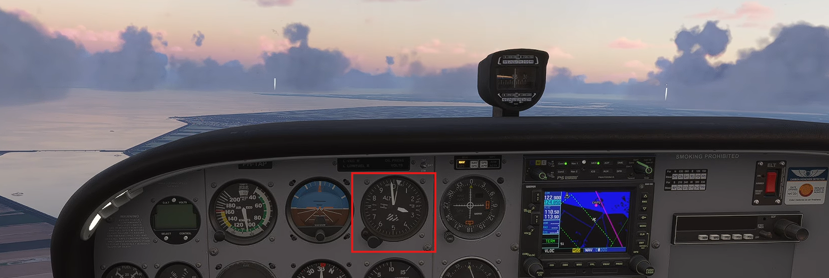
Why does the altimeter works like this?
In modern times like 2026 it would be much easier to use proximity sensors or GPS to calculate your altitude. This doesnt work with sensors at the bottom of the airplane, as we would have a different altitude every nanosecond and as other traffic in the vicinity which we want to avoid. Also, based on knowledge and earlier incidents the aviation world agreed on the pressure-based version as pressure is always there. Even when having a engine fire, electrical error and all sorts of problems at once.
Altitude indicator errors
The altitude indicator can also have some minor errors, where the indication is not 100% correct to the actual altitude:
- Instrument errors : These errors come from that every instrument has some minor deviations from actual scales. Mechanical components are dependent on friction, temperature differences and such.
- Atmospheric deviations : As the atmosphere is never 100% according to ISA, we can expect the altitude indicator to not be 100% like that, the true altitude is somewhat different to the indicated altitude.
Generic instrument errors
No measuring instrument is 100% perfect, and some minor instrument errors can affect the indication:
- Room and friction : The mechanism can have some room and some friction, by using high quality parts this can be minimized but is never zero.
- Temperature-influence : Parts expand and contract based on the environmental temperature.
- Position error : Error in the position of the probe can also affect the indication. This is especially the case with instruments measuring the pressure like the pitot probe and the static port.
- Indication-delay : At fast altitude changes, the altitude indicator for example will be behind of the actual altitude. With rapid descends, the indication will be too high and with rapid climbs too low.
Pressure deviations and Altitude
According to ISA the pressure on sea level is 1013,25 hPa. If the actual pressure deviates from this pressure, an uncorrected altitude indicator will indicate a wrong altitude. This is why we have a dial and reference points.
A rule of thumb is that every decrease of 1 hPa is a 30ft difference.
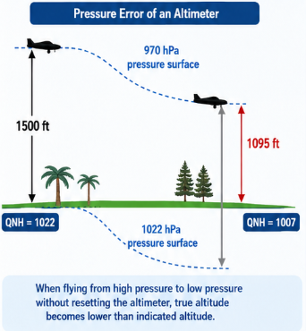
This is also applicable to situations where you fly from country A with a QNH pressure of 1022 hPa to contry B with QNH pressure 1007 hPa. This causes the true altitude to decrease where your indicated altitude will still show 1500ft.
Temperature deviations and altitude
A pressure altitude meter will indicate the true altitude only in ISA conditions. If the temperature increases above ISA, the coloumn of air will expand and the true altitude will become higher than the indicated altitude. Warm air expands and causes the air pressure to drop, and as the altitude indicator is a pressure-meter, this is c=exactly the cause.
- High temperature (than ISA) = higher true altitude
- Low temperature (than ISA) = lower true altitude
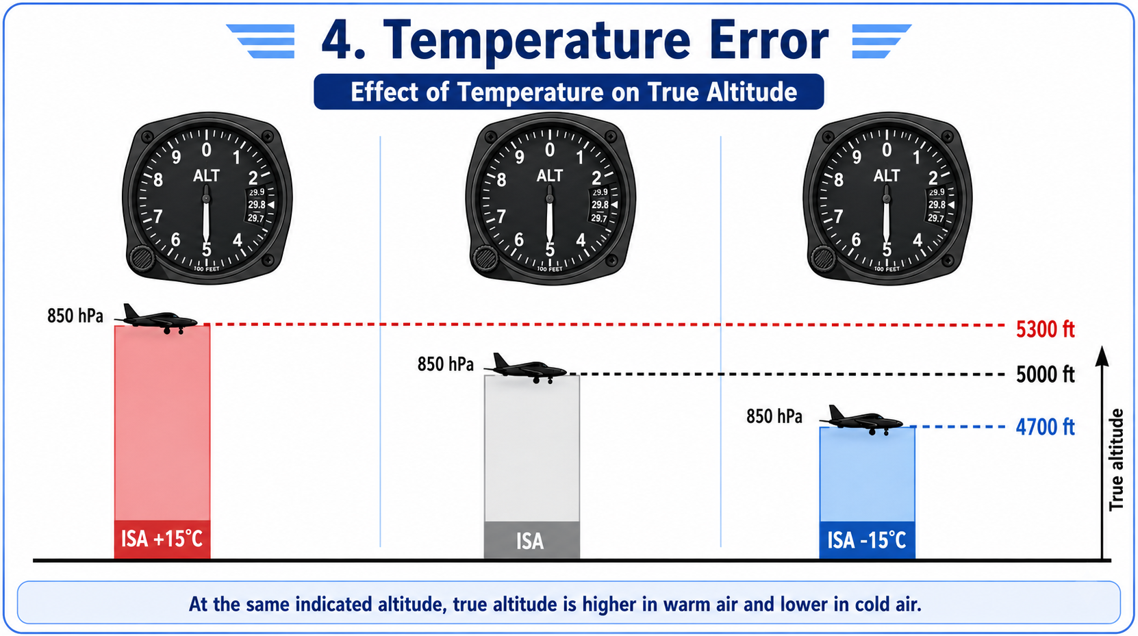
Vertical Speed Indicator (VSI)
The vertical speed indicator will indicate if the plane is ascending, descending or in straight and level flight. This does it by indicating how much feet you descend or climb in one minute. The instrument is always zero-centered and goes up when climbing and goes down when descending. Basically following the flight path of the plane. The VSI measures the rate of change of static pressure and has a short delay from pressure change to indication in the cockpit, as it relies on measuring pressure difference with the pressure from some seconds before.
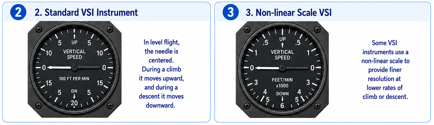
This works almost the same as the altitude indicator, by connecting the static port to the instrument, but in this instrument, the static port is connected to both the diaphragm/aneroid and the instrument-case. The air into the instrument case is filled up with a calibrated opening and delayed, so the instrument measures the pressure difference of the air according to the pressure of some seconds ago. This calibrated opening is also called the capilair.
This is also the cause of why this indication has some delay/lag, as the instrument-case is slowly filled with the air.
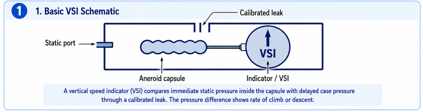
Instrument errors
Because the VSI is connected to the static port, and this can have errors when maneuvering and position errors, this can cause some instrument errors to this indicator. Temperature also have a minor deviation on the indication. Lower temperature cause the needle to give lower indications than with high temperatures.
The VSI also has some delay/lag as already described. This delay increases with the size of the climbd/descends you make.
Gyroscopic instruments (11)
Some aircraft instruments rely on the properties of a gyroscope. This is an efficient way to have the indicators working. In many older or traditional light aircraft, the attitude indicator and heading indicator are powered by an engine-driven vacuum system, while the turn coordinator is electrically powered. Modern aircraft can use electrical gyros or digital AHRS systems instead. This is done for redunancy, so if one system fails you still have all types of indications.
The indicators which uses gyro’s to function:
- Artificial horizon (ADI)
- Heading indicator (non magnetic)
- Turn coordinator
We can use the Turn coordinator and magnetic compass in situations the pneumatic gyro’s are not working, and we can use the attitude indicator when the electrical gyro is not working. Clever built-in fallback.
Gyroscope properties
A gyroscope is a very fast rotating disc at speeds between 20.000 to 25.000 revolutions per minute and is used in some cockpit indicators because it has some physical properties:
- Rigidity in space ( standvastigheid ) means that a spinning gyroscope wants to stay in the same position or attitude while it is rotating. Because the gyro keeps its position, it is an excellent application in an artificial horizon. In the instrument, the gyro is set level with the real horizon. As the aircraft climbs, descends, or turns, the aircraft moves around the gyro, but the gyro itself tries to stay upright. This allows the pilot to see the aircraft’s attitude compared to the horizon, even when flying in clouds or when the real horizon cannot be seen.
- Precession is another important property of a gyroscope. It means that when a force is applied to a spinning gyro, the reaction does not happen at the same point where the force is applied. Instead, the reaction appears about 90 degrees later in the direction of rotation. In simple words: if you try to push a spinning gyro in one direction, it reacts in a different direction. This effect is important in aircraft instruments because it can cause small errors in gyro instruments over time. Because of this, some gyroscopic instruments need correction systems to keep them accurate.
So in short:
- Rigidity in space means the gyro wants to stay where it is.
- Precession means the gyro reacts in a different direction when a force is applied.
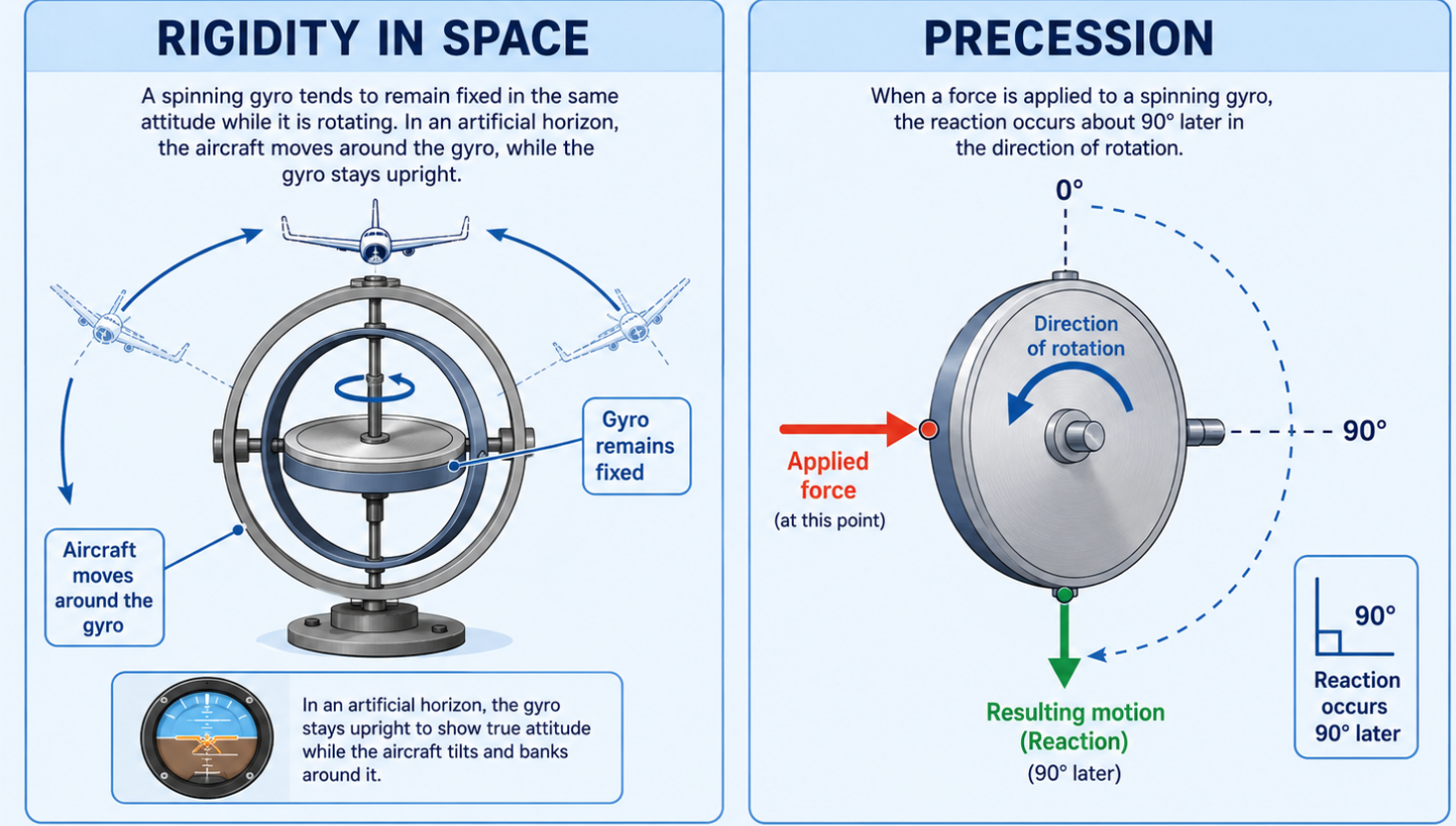
To learn more about gyroscopic instruments, I recommend this video: https://www.youtube.com/watch?v=hVsx4XWafXg
Gyroscope powering
The gyroscopes are powered very often in two different ways for redundancy:
- Pneumatic : This means the gyro is powered by an engine driven vacuum-pump. This pump produces a very powerful flow of air, causing the gyro disc to rotate. This is done in smaller aircraft like the Cessna 172 for the Artificial Horizon and Heading gyro’s.
- Electrical : This means the gyro itself has a electrical engine to rotate the gyro disc. This is done in smaller aircraft like the Cessna 172 for the turn coordinator only.
In the cockpit we have a “Suction”/Vacuum indicator, which is this vacuum pump. This tells us more on how much we trust our vacuum-powered gyro’s.
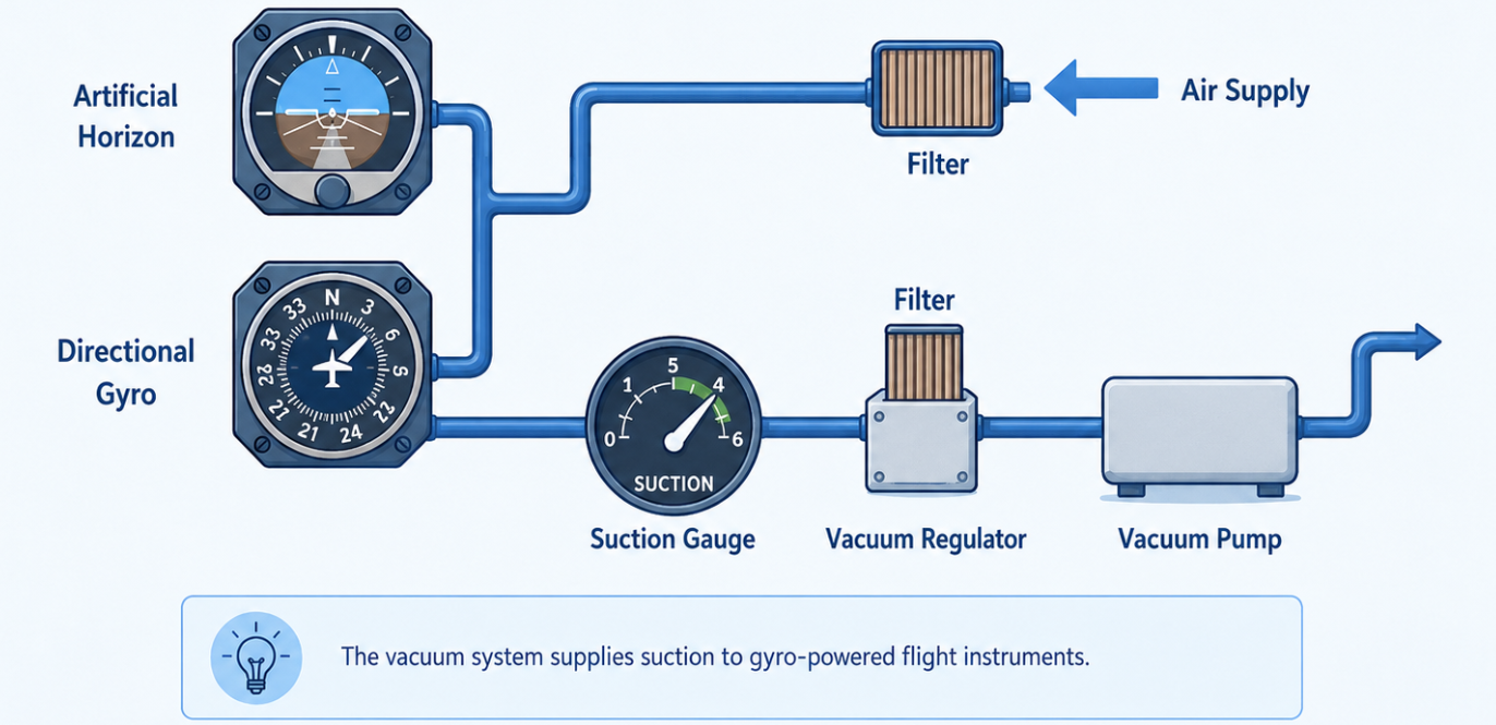
The pump itself is driven by the engine, so the pressure itself is dependent on engine rpm. To prevent the pressure from being too low, we have a pressure regulator called the cacuum regulator to keep the pressure at a constant value. To also secure this pump, this is also equipped with a filter. The suction gauge is the pressure difference before and after the instruments and is indicated in inches of mercury (InHg) which is often around 5 InHg. Higher values give more under-pressure and a lower total pressure.
Errors in the vacuumsystem
As the vacuum-pump is driven by the engine, it can have errors:
- Low indication: This can be caused by an inoperative vacuumpump, a blocked inlet filter or a defect indicator
- Flying at low RPM or high altitude can also give a too low indication as the vacuumpump cannot build up enough pressure
- High indication: This can be caused by an inoperative pressure regulator or blockage in the filter/regulator
When flying VFR, these errors are not that huge problems. We still have an engine pushing us forward, we still know our altitude and speed and we can continue with our magnetic compass. However, flying IFR makes a difference, as we cannot see the horizon so we don’t know our roll axis. We can use the turn coordinator as backup for banks but this is much harder as the indication is not as precise as the artificial horizon.
Gyro drift
A gyro-disc which can move freely will keep a fixed attitude in the space. In real life, some drift or wander can happen. We have three types of gyro drift:
- True drift: The cause of true drift is the construction of the instrument. Due to friction in the lowers, imperfections in the construction and imbalance in the gyro and temperature-effects can cause the gyro to slowly drift from its fixed position.
- Apparent drift: The gyro has a fixed attitude in the space, but this does not equal to a fixed attitude to the earth. The earth rotates and doesnt have a fixed attitude. This causes the gyro to slowly changes it attitude, which is called apparent drift, and can be maximum 15 degrees every hour, as this is also Earths rotation speed (360 degrees per 24 hours is 15 degrees per hour).
- Transport-drift: The plane flies over the earths surface and also influences the apparent drift due to its movements. The size of this drift component is dependent on the speed and direction you fly to.
Attitude indicator (artificial horizon)
The attitude indicator shows the attitude of the plane based on the natural horizon. With this instrument, we know the attitude without looking outside. We can see the following parameters on this instrument:
- Rolling angle
- Pitch attitude
- Horizon and the roll-angle of the plane
In the attitude indicator, a horizontal placed disk spins in a vertical axis.
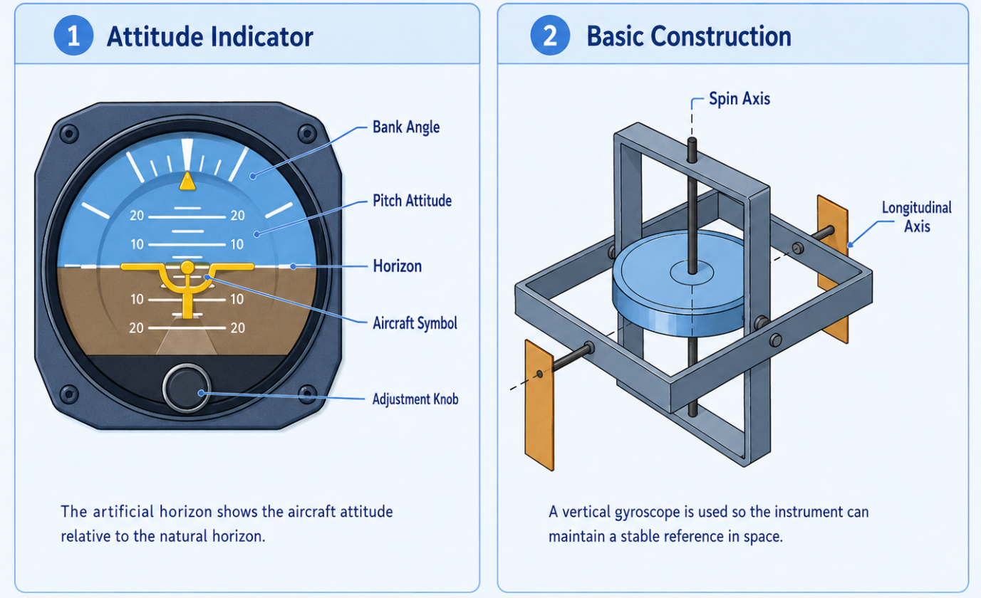
In this way, the attitude indicator is set to a earth bound gyro. A copy of the visible horizon.
Indication errors
Pneumatic attitude indicators can have some errors while accelerating and while turning. When holding this attitude for a short while, the instrument will correct itself so it can indicate too much roll and acceleration.
During the taxi checks on the ground, we will steer left and right to check if every instrument is working correctly, but the attitude indicator must be stable and level. If this indicator moves during this check, the indicator is defective and a choice must be made to fly with it or not. When not expecting clear weather and perfect visibility, great chance its not a great idea to fly with this defective indicator. Also, we can only trust these pneumatic indicator if the suction pressure is within accepted limits.
Directional Compass/Gyro
Just like the attitude indicator, the directional gyro which we use as a copy of your magnetic compass is relying on the rigidity in space. This has a vertical disc spinning in a horizontal axis.
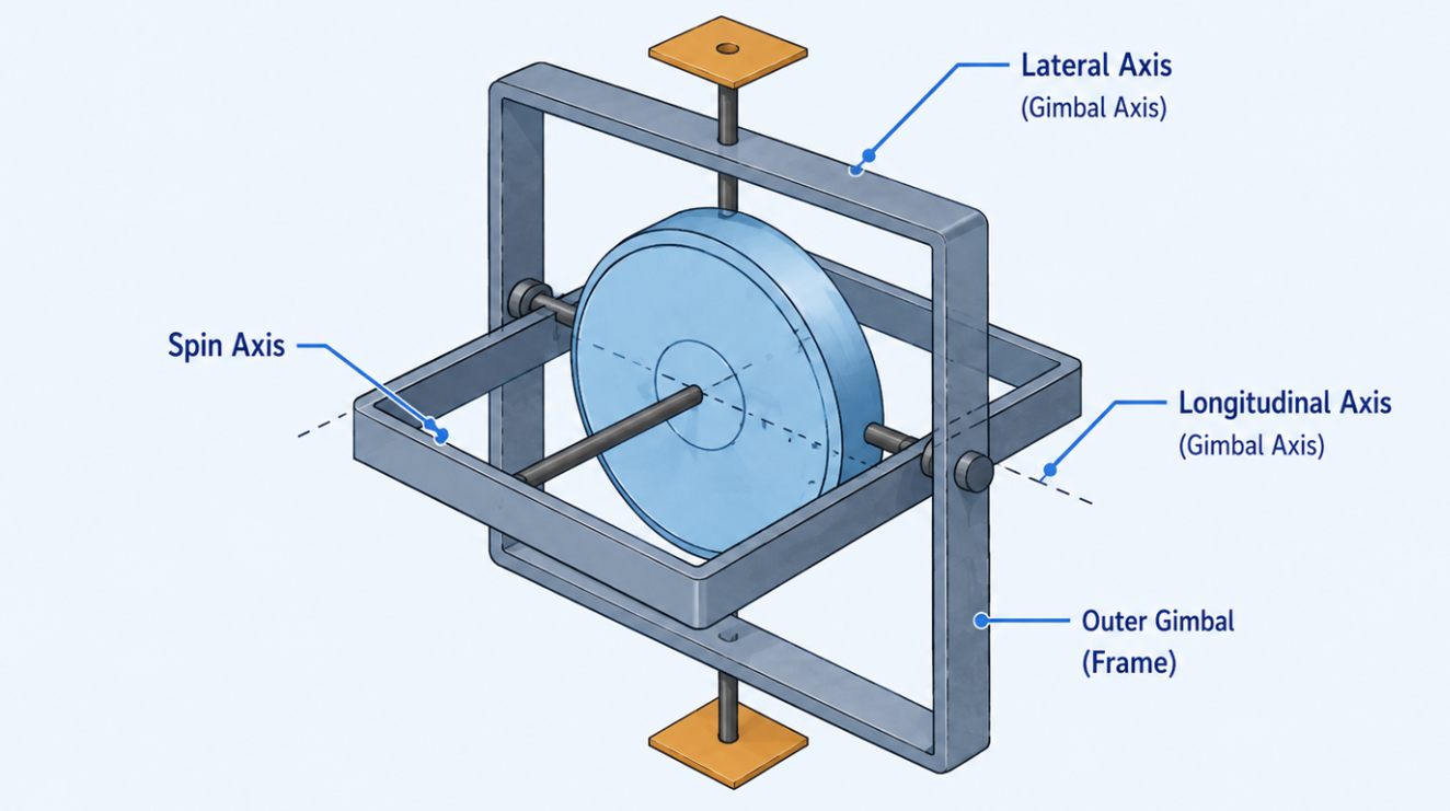
We have to set this compass every several minutes to the same heading as the magnetic compass to make the directional compass show the compass heading. This does not represent the true (chart) heading.
The gyro compass is much more reliable in turns and has a overall more stable indication. Magnetic compasses have turning errors and do not indicate the right heading in turns. It also doesn’t work that great in turbulent air. The gyro compass does not have the same magnetic turning and acceleration errors, but it can drift over time and must be regularly checked and aligned with the magnetic compass.
Turn coordinator
The turn coordinator gives us information about the direction and speed we make our turns. The rate of turn (ROT) is the amount of degrees per minute we change direction. We also have a “water-level” like indication if we make coordinated turns, or how to make them based on your current flight actions. The turn coordinator is sensitive to rolling and yawing movements, so the instruments does indicate turns while on the ground. This is one of the checks we do on the ground during taxi.
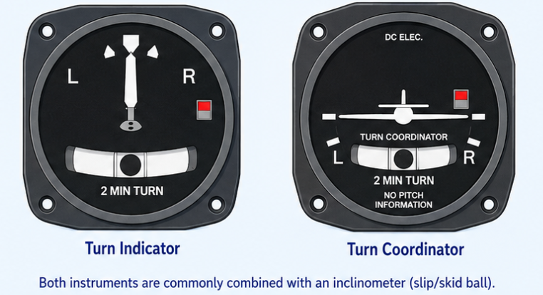
This instrument is the only electrical powered gyro instrument in most planes and is used as fallback when the pneumatic instruments are not indicating correctly. It also has a electrical switch/power indicator, as the instrument is powered the red block will disappear but when the power is broken, a red indication will show, telling you to not use the instrument.
The rate of turn is indicated in rates. A rate-one turn is 180 degrees in one minute, 360 degrees in 2 minutes etc.
How to use the turn coordinator
The turn coordinator shows the rate of turn, not the actual bank angle. The bank angle needed for a rate-one turn depends on airspeed. It also has a ball to show if you make a coordinated flight. A rule of thumb for this is “step on the ball”, meaning to press the pedal on the side where the ball is to get it in the middle.
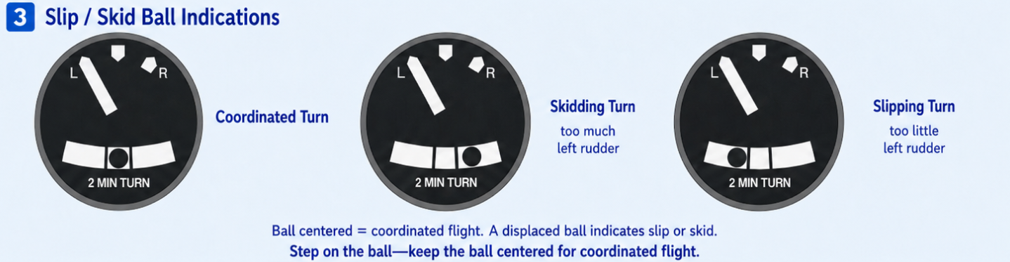
When making coordinated turns, you fly with less unnecessary drag and better passenger comfort. Slipping or skidding in turns increases drag and can be unsafe, especially close to stall speed. Air will then not come from straight forward.
- Slipping (slippende bocht):Too less rudder input
- Skidding (schuivende bocht): Too much rudder input
Remember this sentence: Step on the ball
Summary of gyroscopic indicators
To summarize all indicators and information described above, I have made this table:
| Instrument | Main purpose | Powered by | Properties | Mounted | Axis of rotation |
|---|---|---|---|---|---|
| Attitude Indicator (ADI) | Shows pitch and bank attitude | Pneumatic | Rigidity and Precession | Horizontally | Vertical axis |
| Heading Indicator | Shows aircraft heading | Pneumatic | Rigidity | Vertically | Horizontal axis |
| Turn Coordinator | Shows rate of turn and helps identify slip or skid | Electrical | Precession | Vertically/tilted | Horizontal/tilted axis |
Integrated Avionics (12)
In modern aircraft, we can see more and more indicators being replaced by glass cockpits, where all of the instruments we know are being replaced by screens displaying all the needed data. The advantages of screens are pretty much that you can display anything you want and switch through different menus.
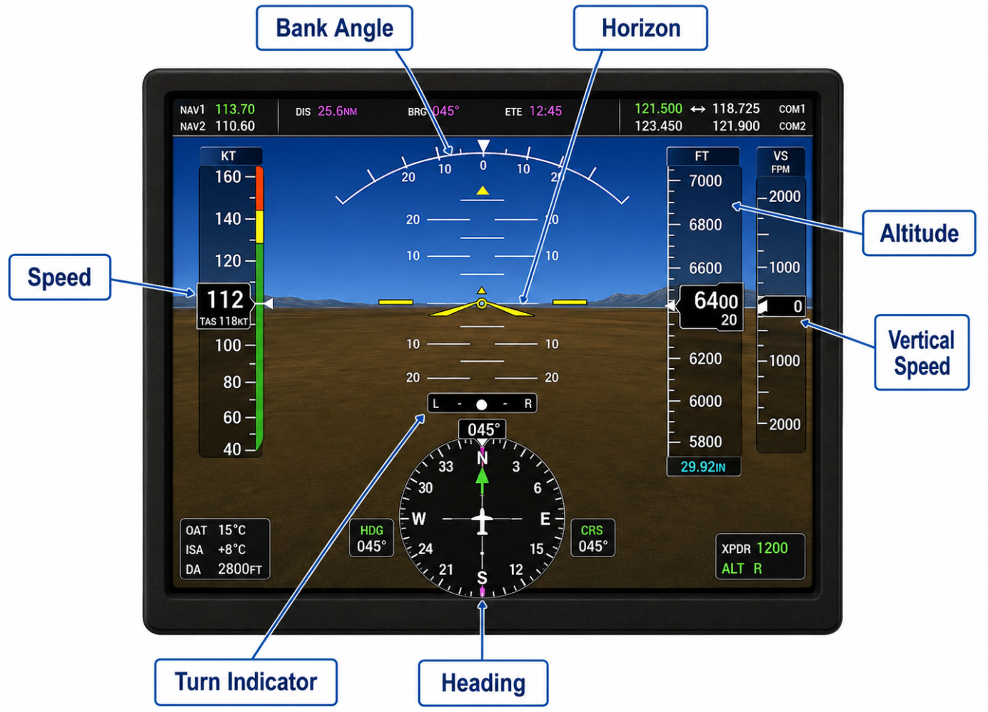
We know two types of screens:
- Primary Flight Display (PFD): This shows the primary flight information, such as airspeed, attitude, altitude, heading, vertical speed and turn/slip information. It can also display things like radio frequencies, navigation information and transponder information, depending on the system.
- Multifunction Flight Display (MFD): This shows mostly a digital map and all the engine instruments like RPM, ammeter, fuel flow, oil temperature and pressure. In most cases you have buttons to switch through various menus and overviews.
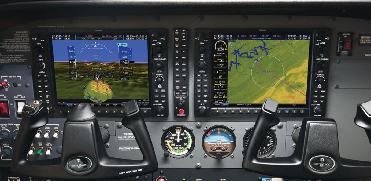
Under the screens we also have some fallback instruments which still work like the how older planes dit it, this is in cases the electrical system or screens fail. We then still know our speed, attitude and heading to land the plane safely.
Air Data Computer
The Air Data Computer (ADC) receives data from the pitot-static system and often outside air temperature. It converts this data into digital information such as airspeed, altitude, vertical speed and true airspeed. Engine data such as RPM, oil temperature and oil pressure normally comes from engine sensors and an engine indication system. We also have a magnetometer which senses the earth’s magnetic field and helps provide magnetic heading information. This is then converted into digital data by the AHRS, which is the Attitude and Heading Reference System.
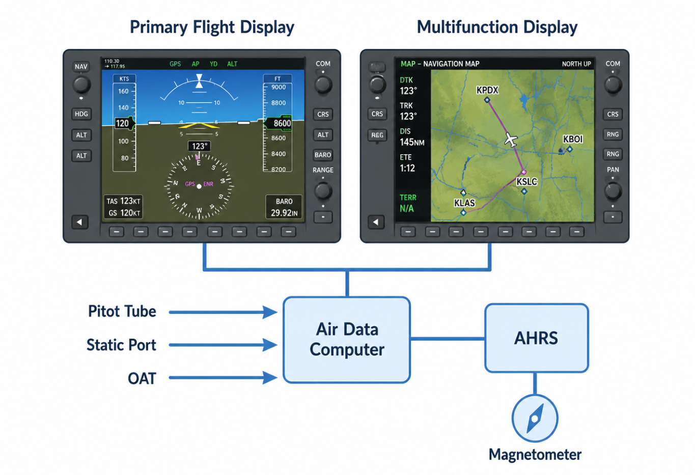
Magnetic Compass (13)
For more information, check out: https://flightblog.justinverstijnen.nl/ppl-theory-nav/#true-north-vs-magnetic-north-vs-compass-north-16
A magnetic compass is working on the sensitiviness of earths magnetic field. With using compasses we have three different references of “north”:
- True north : This is the uppermost part of the globe on our charts and mini-globes and is where the icebears live
- Magnetic north : This is the northern magnetic pole where compasses point to, which is close to true north but at this moment in 2026 there is a 450+km distance between true north and magnetic north
- Compass north : This is the north the compass indicates, but compasses can indicate a small error caused by imperfections and electromagnetic fields called the " deviation “.
Earth has a magnetic field around it, mainly caused by movement of electrically conducting molten iron in the outer core. This causes compasses to align with the earth’s magnetic field and point toward magnetic north. However, the magnetic north pole is somewhat different and is moving from time to time.

Magnetic north
Magnetic north is the direction a compass points to when no local interference is present. Because this magnetic field is mainly caused by movement of electrically conducting molten iron in the outer core, this point changes from year to year. At this moment in 2026 the magnetic north pole is around several hundred kilometers away from the true north pole. The angle between true north and magnetic north at a specific location is called magnetic variation or magnetic declination.
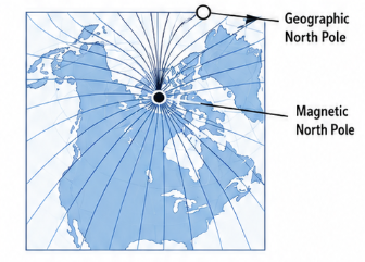
As this variation is different all over the world, we can find this in the AD information in the AIP or in apps like SkyDemon and Aeroweather. On our chart we have isogonic lines which connect different places with the same variation.
Why this is so important, is that on most places the variation will be a few degrees of, but in other places like close to the poles you can get a theoretical difference of 180 degrees between magnetic north and true north, which means you could fly to the complete opposite side if not taken everything into account.
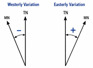
Inclination
Inclination, also called magnetic dip, is the angle at which the earth’s magnetic field points into the earth. Near the magnetic poles, the magnetic field points much more vertically. This makes a magnetic compass less reliable, because the compass card wants to dip instead of only rotate horizontally. We can say that above 60 degrees north or below 60 degrees south, we are close to the poles and the magnetic compass becomes less trustworthy.
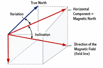
Compass construction
The magnetic compass which we have in our airplane is constructed with some magnets in a rotatable case. This case contains dampingfluid which helps the compass to move slowly and better move factor in turns.
This compass can have some errors due to electromagnetic fields. Also when a plane is parked in the same direction for a long time the compass can give false indications. The aircraft maintenance companies can recalibrate the compass.
Compass errors
A compass wants to line up into the magnetic field lines. Because of the inclination for example in the Netherlands, the magnet also wants to point 67 degrees down. A magnetic compass is constructed so the compass can only move horizontally. But it can have some errors:
- Turning error : During a turn the magnetic compass will not indicate the correct heading
- Acceleration error : During acceleration and slowing down the compass will change heading while this is actually not the case
The magnetic compass is a simple but limited device and should mainly be used in straight, level and unaccelerated flight, or in situations our gyro-based compass, avionics and other devices are not working.
- Turning from north will result in a wrong but then corrected turn
- Turning from south will result in a inverted turn
Turning error
The turning error will be induced by turns we make in a plane. On the northern hemisphere, this can be remembered with UNOS:
- Undershoot North : when turning to a northerly heading, roll out before the compass reaches north.
- Overshoot South : when turning to a southerly heading, roll out after the compass passes south.
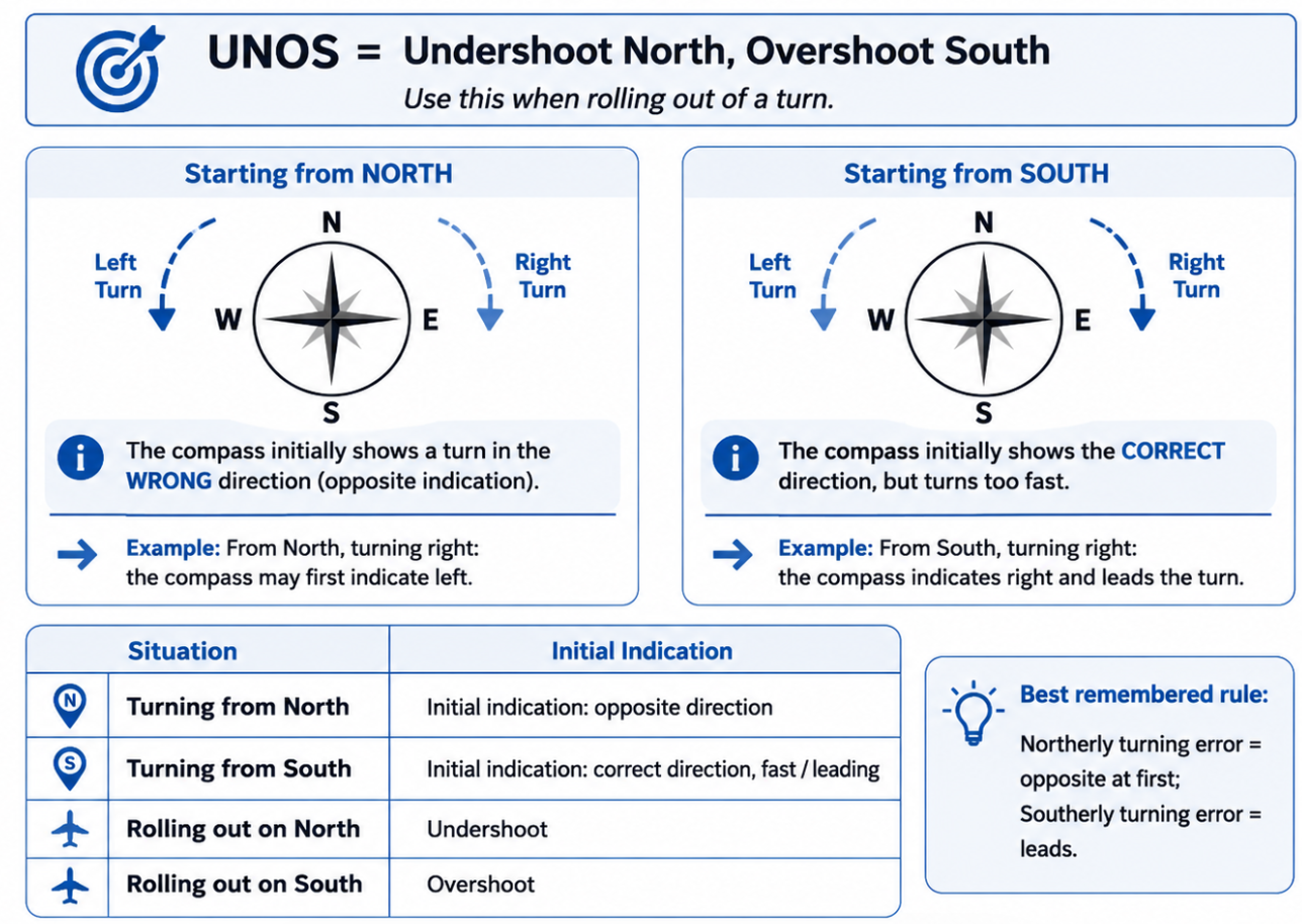
This is because the compass lags or leads during turns, especially on northerly and southerly headings.
Acceleration errors
On the northern hemisphere, acceleration errors are most noticeable on east or west headings and can be remembered with ANDS: Accelerate North, Decelerate South. During acceleration, the compass indicates a turn toward north. During deceleration, the compass indicates a turn toward south. After the acceleration or deceleration stops, the compass indication will settle again.
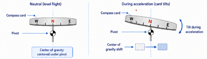
End of the page 🎉
You have reached the end of the page. You can navigate through other blog posts as well, share this post on X, LinkedIn and Reddit or return to the blog posts collection page. Thank you for visiting this post.
Support the blog
