Principles of Flight (POF)
For a live overview of my flight lessons, visit: https://flighttools.justinverstijnen.nl/flightlessontracker
This page can contain a collection of personal notes, steps to remember, finished and unfinished content. Please excuse brevity.
Do not use specific information given like fuel flow, landing/take-off distances for your flights. Always refer to the POH of your exact plane for flight preparation. My information is just for references that I used.
The air is best described as “thin water”. We humanity live on the floor of the air-ocean.
The atmosphere (1)
The atmosphere is the layer around the earth, which is around 100 to 200km from the ground up. Worldwide, we use the International Standard Atmosphere which is a mean set of conditions which will be somewhat different depending on the weather conditions, location etc. This is a mean of the conditions at 45 degrees north latitude.
In the standard atmosphere, we use these characteristics:
- 0ft is at the mean sea level
- The air density is 1,225 kilograms per cubical meter
- The air pressure is 1013,25 hPa (millibar) or 29.92 inches of mercury (inHg)
- The temperature at sea level is 15 degrees celsius
- In the troposphere, the temperature decreases with 2 degrees celsius for every 1000ft up (2 degrees per 300 meters)
- The tropopause is at 36.000ft (11km) and the temperature is -56,5 degrees celsius
- The troposphere and stratosphere contains 78% carbon dioxide (co2) and 21% oxygen
This is a set of conditions, but some numbers can defer in the real world, due to the location or different seasons. Now, lets take a look at the different layers in our atmosphere:
| Layer | Altitude | Characterstics | Temperature gradient (ISA) |
|---|---|---|---|
| Thermosphere | 280.000ft and up 85km and up | Thin air and high temperature due to solar radiation. Auroras happen in this layer | Increases with altitude |
| Mesosphere | 160.000ft - 280.000ft 50km - 85km | Meteors burn up in this layer, coldest layer | 0c to -90c |
| Stratosphere | 36.000ft - 160.000ft 11km - 50km | Contains the ozone layer, stable air with some jet streams at the bottom | -56,5c to 0c |
| Troposphere | 0 - 36.000ft 0 - 11km | Bottom layer at the ground of earth and where weather/clouds take place | 15c to -56,5c |
This is a repeat of the information already learned in the Meteorology course. For more information, check out
Air Pressure
Air pressure is a result of the mass/weight of the air. Because there is so much air above the earth which compresses close to the ground, areas with a lot of air molecues will be created. You can see this as a tower of jenga you played before. The weight of all the bricks pushes on the lower layers of bricks.
On earth we have several high pressure areas and low pressure areas which are an result of temperature differences. High pressure areas always wants to go to low pressure areas, just like when you pump up a tire and let go the vent. The air from the high pressure area inside the tyre will go to the outside, low pressure area.
- In high pressure areas: cold air falls to earths surface, and cold air has more air molecules
- In low pressure areas: warm air from the surface rises, and warm air has less air molecules
So air pressure actually indicates the volume of air molecules in the area. The higher the pressure, the higher the volume of air molecules.
High pressure (H) and low pressure (L) areas are not absolute numbers, but relative to each other. For example:
- 979hPa (L) vs. 1013hPa (H)
- 1013hPa (L) vs. 1035hPa (H)
Air Pressure when elevating
When going up into the air, the air pressure will decrease like seen in the graphic below:
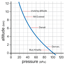
For reference, we will use this numbers:
- Every 30 feet up in the air represents an hPa loss in air pressure
- Example: 1013 hPa on sea level (0ft AMSL) means a mean pressure of 1000 hPa at 390ft altitude
As this is an exponential relationship, this will guide you through the first 10.000ft (3,048km) in altitude, after that this trick does not longer work correctly of course. Some good rules of thumb:
- 5.000ft altitude: 75% (3/4) from ground pressure
- 18.000ft altitude: 50% (2/4) from ground pressure
- 34.000ft altitude: 25% (1/4) from ground pressure
For more information about Pressure and Density altitude, check out: https://flightblog.justinverstijnen.nl/ppl-theory-nav/
Pressure Altitude
Pressure altitude is the altitude corrected to the International Standard Atmosphere, namely 1013 hPa (which is also called QNE). For performing take-off calculations, we will want to know how our plane performs which can be different with different pressures. This is a live indicator of being above or below earth’s standard atmosphere.
In short:
- Higher pressures (Low altitiudes): Better engine performance, better propellor performance and more lift
- More oxygen and more air molecules
- Lower pressures (High altitudes): Less engine performance, less propellor performance and less lift
Pressure altitude examples
In an airport which mostly is lower or higher than mean sea level, there will be a small correction needed. For example, our airport is at 17 feet above sea level, and the actual pressure is 1032 hPa on sea level at a day with nice weather, the pressure altitude is -489 ft. This means our take-off performance will be better as we have more air molecules which is better for our engine.
In the same example with a pressure of 968 hPa on sea level, we will have a pressure altitude of 1238ft. This means our aircraft will perform as it takes off at 1238ft above sea level, which will have some disadvantages. As there is less air, we will need a longer runway, our engine performance is less and our lift will be less as there is less air. However, flying in relative high pressure altitudes is good for having speed, as drag decreases in lower pressure.
As you can already see, this example gives two completely different scenario’s with around 1700ft difference. In countries like the USA where airstrips can be at 5000ft altitude, the pressure can be a huge difference which we must take into account.
Check out this tool to calculate and visiualize Pressure/Density altitude: https://flighttools.justinverstijnen.nl/pressuredensityaltitudecalculator
Density altitude
Now we know the pressure altitude, we need to correct it for Density altitude, because warmer air is thinner than colder air. This is because warmer air expands, just take a look at a hot air balloon. This means that on 5000ft pressure altitude and on a hot day of 35 degrees, the density altitude (also known as “performance altitude”) will be almost 9000ft. So we can expect our plane to behave as it is on 9000ft in normal ISA conditions.
Thinner air means less oxygen and less air molecules, denser air means more air for lift for both propellor and the wings. Less oxygen also means less engine performance but a higher true airspeed due of less resistance from air molecules.
To calculate the density altitude from pressure altude, you can use the E6B or the tool below:
Check out this tool to calculate and visiualize Pressure/Density altitude: https://flighttools.justinverstijnen.nl/pressuredensityaltitudecalculator
Tip: Use an E6B calculator for a quick and thorough calculation of Density altitude based on the outside air temperature (OAT) and pressure altitude.
Fundamentals of Lift (2)
Lift (draagkracht in Dutch) is a component that keeps a plane in the air. This is the upward force that fights the gravity/weight of the plane. It works basically as the wind flows over and under the wing. As the air over the wing goes faster and under goes slower, it will combine at the end of the wing. Lift is also the component that will compensate for the weight of an aircraft (gravity). This means, how more heavy the plane is, the more lift it needs to produce to fly.
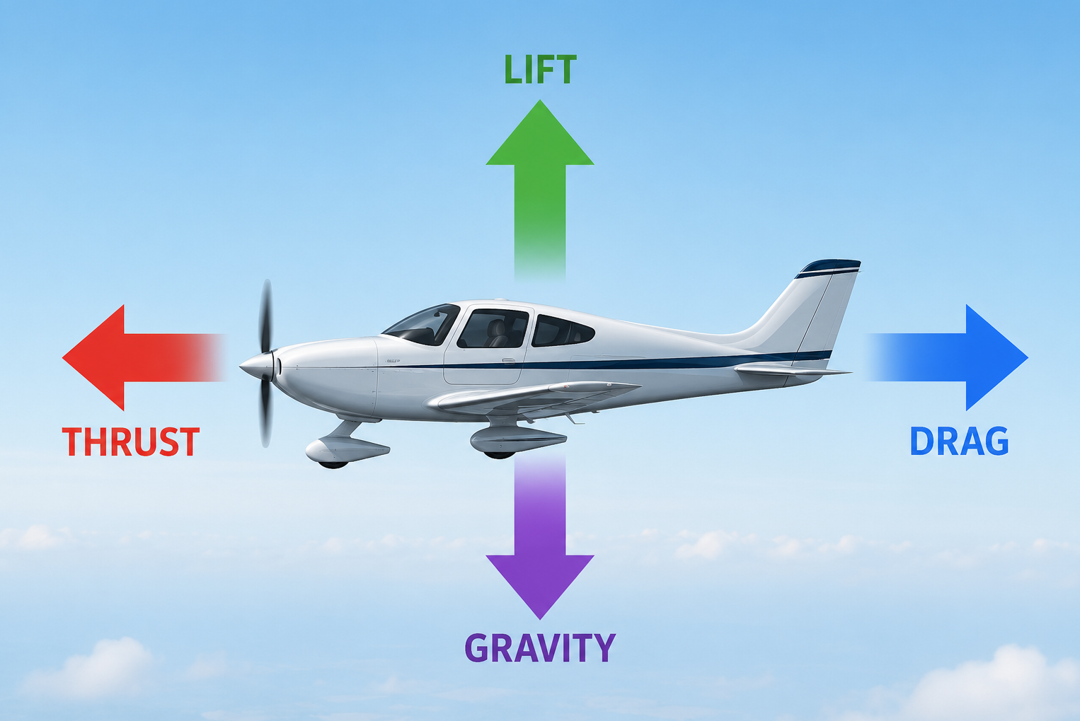
The two primary causes of lift are:
- Pressure differences: under the wings the air pressure increases, wanting to go to the low pressure area above the wing
- After the trailing edge of the wing, the air goes down, under the wing the air goes up
We can explain the air pressure differences induced by lift because of 2 elementary laws:
| Law | Definition | Formula |
|---|---|---|
| The continuity law | A conserved quantity cannot disappear or appear spontaneously; it can only move from one place to another.In fluid flow, this means the amount of mass entering a system must equal the amount leaving it, as long as nothing is added or removed inside. That is why a fluid flows faster when it passes through a narrower section. | V₁ × A₁ = v₂ × a₂ |
| Bernoulli’s law | In a flowing fluid, an increase in speed is accompanied by a decrease in pressure, provided the flow is steady and friction losses are negligible.Bernoulli’s law explains how that increase in speed is related to a decrease in pressure. Compare this to pinching a garden hose. | Ptotal = Pstatic + Pdynamic = Constantp + 1/2 ρ V² = Constant |
Both laws describe that fluids (including air) in a narrow area will go faster and has a lower pressure. This helps us better understand how an aircraft flies.
How an airplane generates lift
Lift works basically with these 4 components:
- Wind velocity: The more headwind (speed) you have, the more air and air molecules will hit your wing. This pushes the wing upward where the wind will then be directed to the ground and changes the velocity. Changing the direction and velocity of this wind has a reaction which is lift force.
- Angle of Attack: The angle of attack is the angle of the wing hitting the wind. By default, planes have a little angle of attack of a few degrees but we can increase this with the yoke (steer) of the plane
- Drag: The drag component is how much air resistance we have in a particular situation. The higher the angle of attack, the more drag and how harder the engine must work to compensate for it, which can evantually result in a stall
- Lift force: The lift force is the resultant of the wind velocity, drag and the angle of attack and states how much the wing is pushed up
Let’s take these 4 components into a simple drawing:
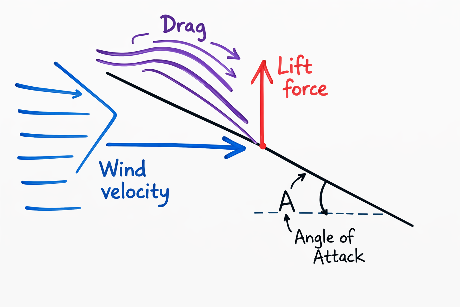
The black line represents the chord of the wing. This is the same with the outline of a wing:
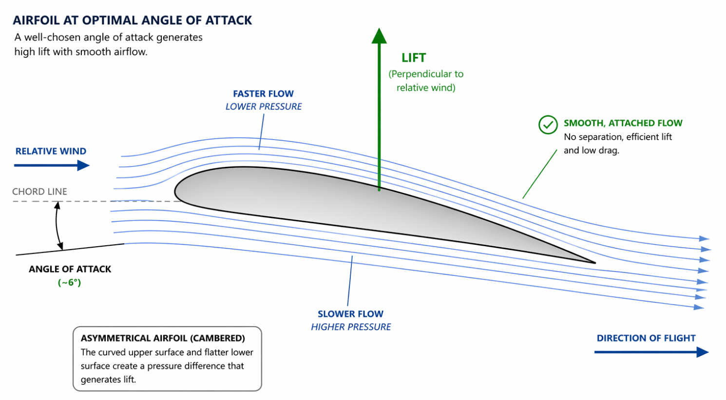
We also have the resulting air-force, which is a line 90 degrees of the wing profile, based on the oncoming wind.
Static and Dynamic pressure
For the example of Static and Dynamic pressure, I will stick to the example of a garden hose, pinched. This results in two things:
- Static pressure (A): This is the air pressure in the hose which will decrease when narrow and will increase again after the narrow part is over
- Dynamic pressure (B): This is the pressure of the water, the speed of the water, and this increases at the cost of static pressure
Take a look at this drawing, which makes more sense:
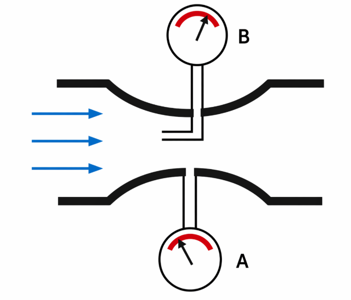
This basically works the same as the pitot-static system of an airplane, the static port measuring the static air pressure, as the pitot probe measures dynamic pressure. Inside of the measurement systems, there will be calculated the results which are Indicated Airspeed (IAS), Altitude and Vertical Speed (VS).
Dynamic pressure is measured with this formula:
- “P = q = 1/2 ρ V²”
This means:
- P: Total pressure
- Q: Dynamic pressure
- 1/2 ρV²: Also dynamic pressure but explained granular
Bernoulli’s law states that for example water or air going into a narrow space at a certain speed, will also come out of that narrow space with that certain speed.
Air flow around a wing-profile
The air will flow around a wing-profile. Because of the leading edge of the wing, the incoming air will divert up and down, bringing the flow-lines closer together.
Just like the two laws already predicted, the airflow will increase and the static pressure will decrease. At the leading edge of the wing, the lines will be closer together. Here the pressure is relatively low. Near the trailing edge of the wing, the flow lines will be less close. The speed of the airflow decreases and the pressure increases.
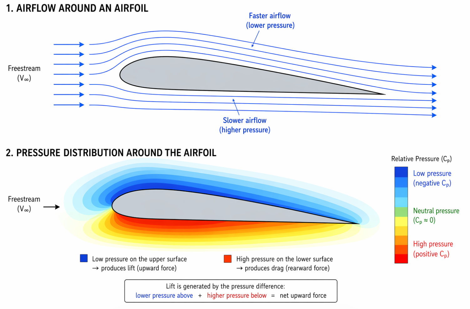
Under the wing, the airflow will have to make a smaller angle and path, causing the air to move at a slower speed but at an higher pressure.
Upwash and Downwash
The upwash is an uplifting movement as result of the pressure differences. The leading edge of the wing needs to split the airflow. This point is called the “stagnation point”, the point of air coming to a small temporary stop and then leaded over or under the wing. In the picture below, you can see that the airspeed is 0 at the stagnation point.
The downwash is a descending movement of the airflow after it hit the wings. As Bernoulli’s law already stated, the dynamic pressure increases then the static pressure decreases, so the air above the wing goes at a faster speed.
Too see this all put into perspective, view this image:
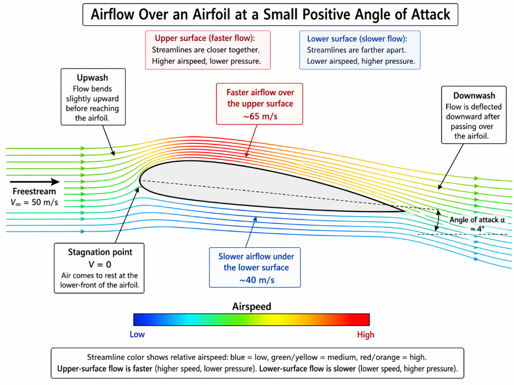
- Airspeeds are a reference
An wing profile described
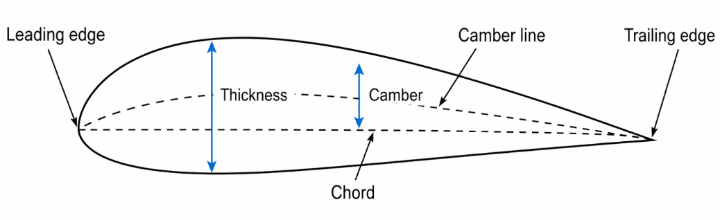
A wing profile has various parts, which we will describe now:
- Leading edge: The frontal part of the wing where the airflow first hit the wing
- Trailing edge: The aft-part of the wing where the airflow leaves the wing
- Chord: The imaginable line from leading edge to the trailing edge
- Camber line: The camber line which is the skeleton-line, is a line which is in the middle of the top and bottom
- Camber: The maximum distance between the camber line and the chord
- Thickness: The maximum distance between top and bottom. This will sometimes be referred as the “thickness-to-chord” ratio
Angle of incidence and Angle of attack
- The angle of incidence (AoI) (Instelhoek) is the angle between the longitudinal axis of the plane and the chord. This is how the aircraft is built and is by design, so the plane generates enough lift in straight and level flight.
- The angle of attack (AoA) (Invalshoek) is the angle between incoming airflow and the chord. This is the pitch angle you can set with the yoke, which controls the elevator.
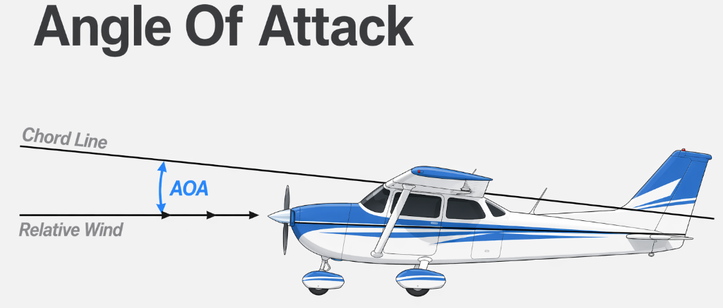
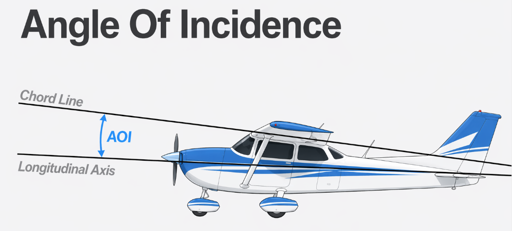
The angle of attack will often be reffered as “α”. It also is an result of sum angle of incidence, the pitch angle and the glide angle.
Glide angle
The glide angle (baanhoek in Dutch) is the angle between horizontal and the flight path. The flight path is the path the center of gravity flies through the air.
The lift formula
The lift formula is an outline of the resulting airforce on a wing profile. Lift is dependent on these 3 things:
- Dynamic pressure of the incoming airflow
- The lift co-efficient
- Wing surface
The formula goes like this:
- Lift = 1/2 ρ V² CL S
| 1/2 ρ V² | CL | Surface |
|---|---|---|
| The dynamic pressure of the incoming airflow (TAS) | Lift Coefficient | The surface of the wing |
So all these components work somewhat together to produce lift. This means the result of all must be positive, where one value can be less or more than another at certain parts of a flight. We will take a deeper look into the Lift components.
Lift terminology
To better understand lift, we have some definitions to look at as these definitions will be used in more explainations later on.
| Definition | Definition (Dutch) | Explaination |
|---|---|---|
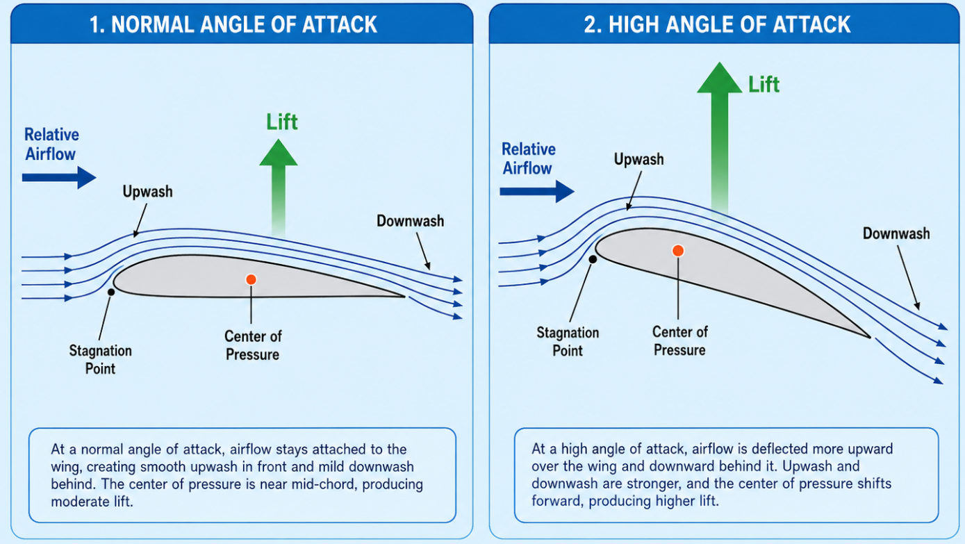
| Center of Pressure (CoP) | Drukpunt | This is the resulting force of the lift of the wing, which we can also call the center of lift |
| Stagnation Point | Stuwpunt | The point at the leading edge of the wing where the airflow is being separated and comes to a stop |
| Upwash | Opwaartse beweging | The ascending airflow after it hits the wing’s leading edge |
| Downwash | Neerwaartse beweging | The descending airflow after it left the wing’s trailing edge |
This picture does shows how these terms work in both cruise and high angle of attack situations.
Dynamic Pressure
The dynamic pressure is the pressure of the free airflow just before the wings. 1/2 ρ V² altogether is a sum of static and dynamic pressure, where V² means only the dynamic pressure. The V factor is equal to the True Airspeed. Headwind is also counted within this V factor, which means that the more headwind, the more lift.
Static pressure in this formula is also very important. This is directly dependent on the static air pressure in the air you fly in. The higher the static pressure, the more lift. This also means that if we climb with a plane to about 34.000ft where the air pressure is about 25% of the pressure on earths surface, you will need much more speed to retain a specific amount of lift.
Lift coefficient
The lift coefficient is a sum of the angle of attack, amount of lift and drag. In a graph, this looks like this:
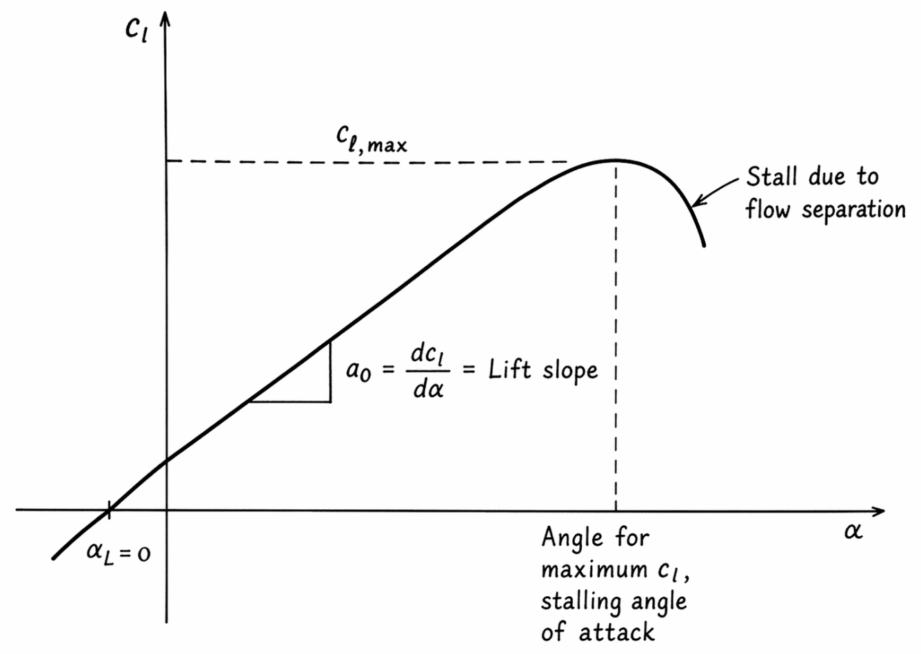
- A fun fact is that because of the angle of incidence of a Cessna 172, a plane wil always have a higher angle of attack than 0.
This graph outlines that the more angle of attack we have, the more lift. However, there is a bount that this stops which is called the critical angle of attack. In a Cessna 172, this is around 15-16 degrees nose up. Pulling even more on the yoke causes the plane to stall and dip from the sky. This can be very dangerous at lower altitudes.
A high angle of attack results in the air not gluing anymore to the wing but to transform into rotor flows. To get a better view of what exactly happens:
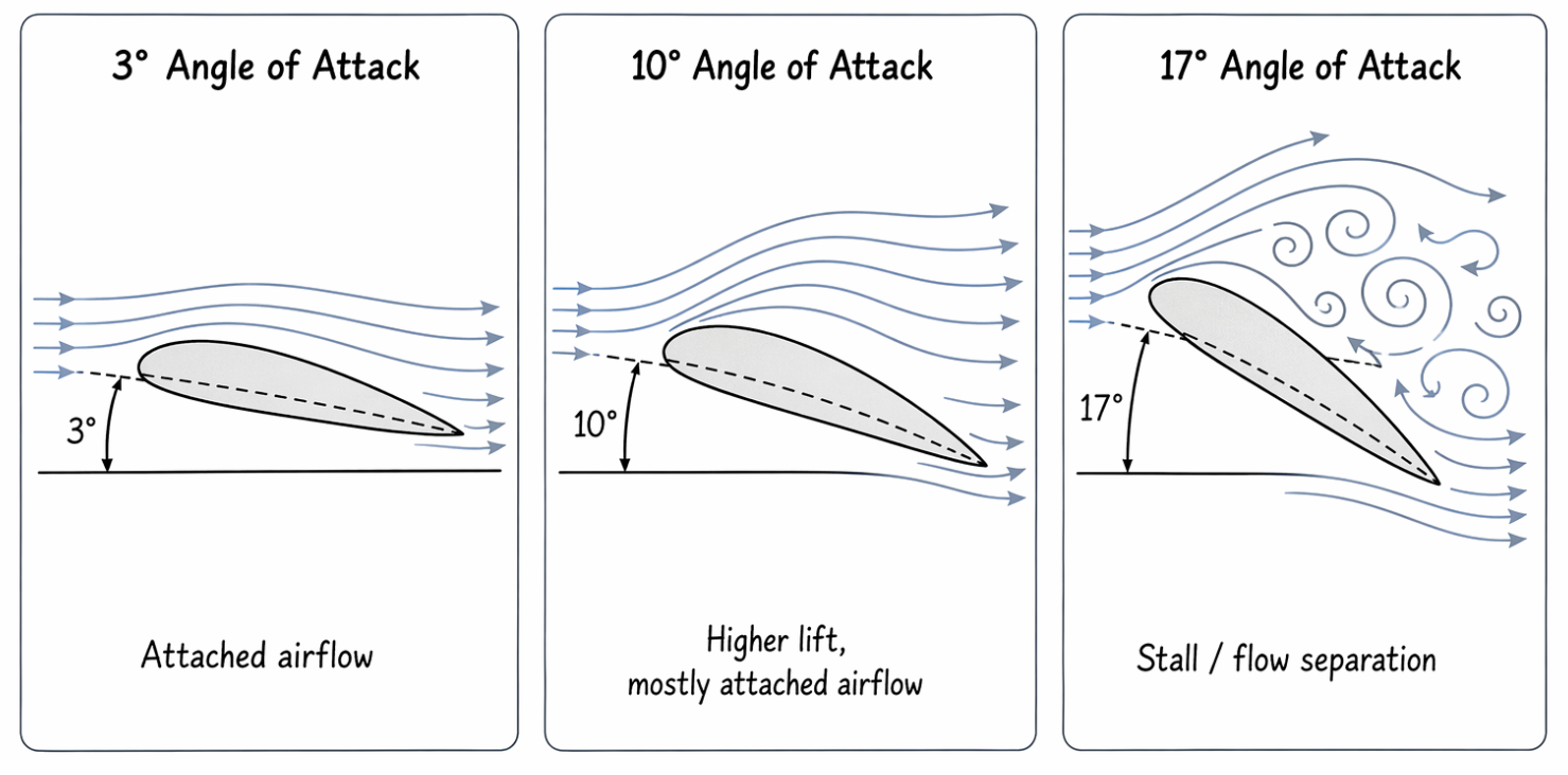
Wing Surface
The wing surface is a factor that directly influences the lift of a plane. In the formula, this will be in the value square meters (m²).
How bigger a wings’ surface is, the more lift it can deliver. We can also do some things with our wings to produce even more lift as they increase the wing surface area. Think about:
- Flaperons (flaps)
- Slats (on airliners)
We set flaps on take-off to produce more lift at a lower speed. This means we need less runway to take-off from. When landing, we use more flaps to create more drag and decrease the speed. Flaps help us in these parts of the flight to have more time, see the runway a lot better and to descend in a much steeper line.
Indicated Airspeed and Lift coefficient
Then in straight and level flight, there is a great connection between the speed and the lift coefficient. The lift equals the weight of the plane and the speed is higher than the amount of drag. However, if the angle of attack increases -> the lift coefficient will also increase. If preventing that the lift increases, the airspeed must be decreased.
- A high speed needs a low angle of attack
- A low speed needs a high angle of attack
Symmetric and asymmetric wing profiles
- An Asymmetric wing profile is where the top of the wing has more camber, this is what most planes have
- A symmetric wing profile is where the top and bottom of the wing are the same, mostly in aerobatic planes
This also means something for the lift coefficient and the angle of attack performances. For example, a symmetric wing profile will start with 0 lift coefficient. This gives it somewhat less lift than an asymmetric profile, as shown in this graph:
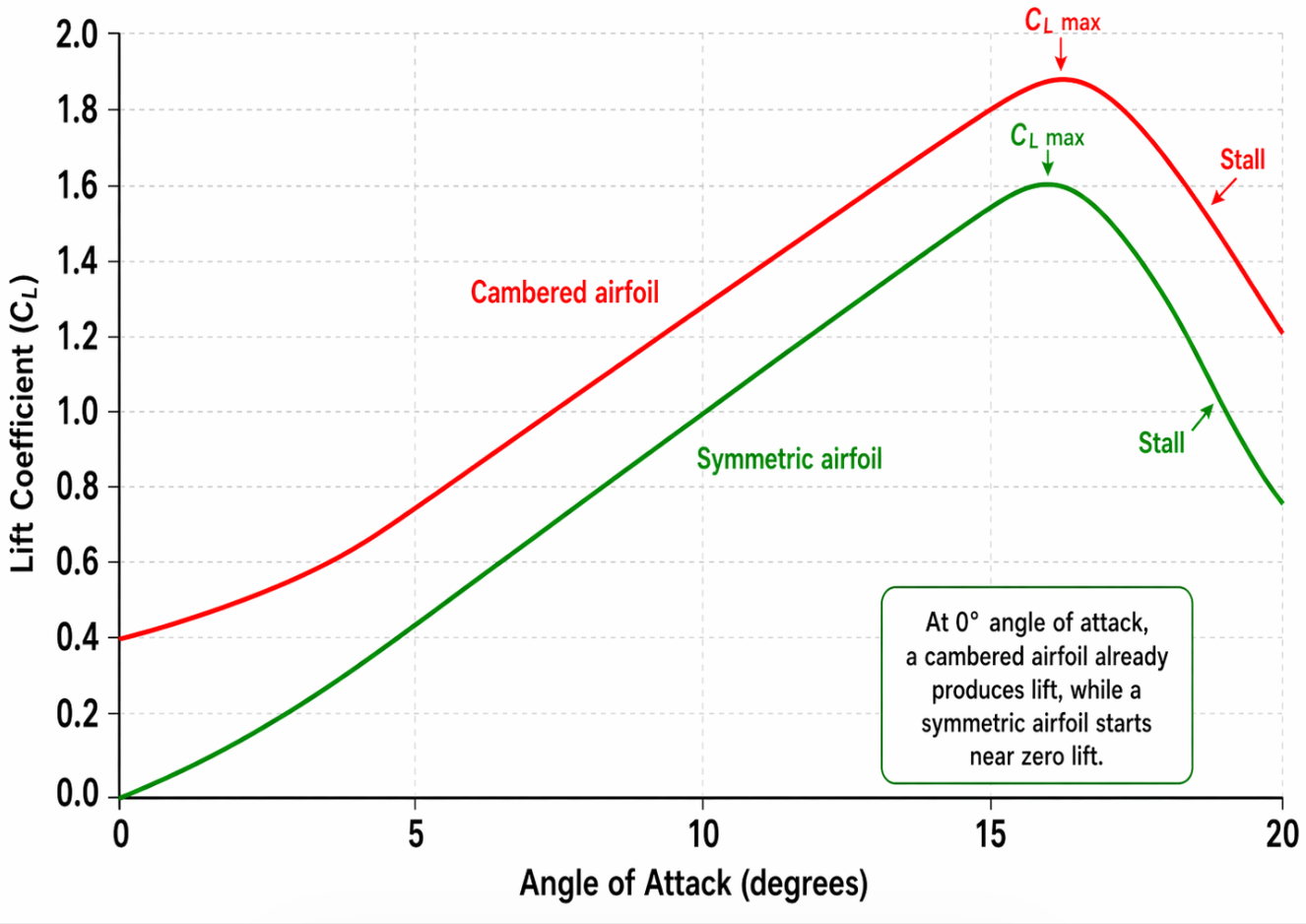
- Red: Asymmetric
- Green: Symmetric
Here an asymmetric wing profiles will eventually reach a lift coefficient at a negative angle of attack.
Three-dimensional airflow over a wing
The airflow over the wings looks like this in three-dimensional setting:
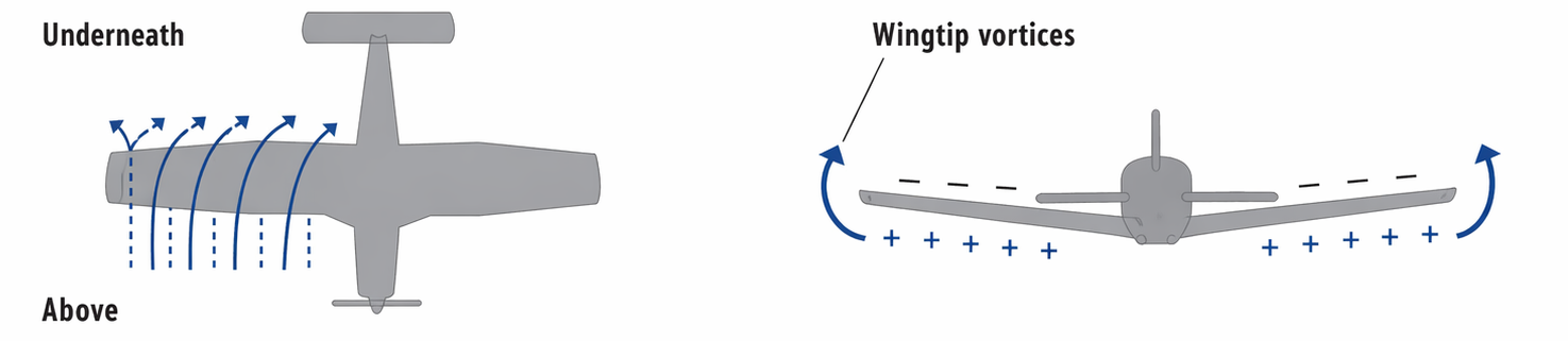
On the left, the airflow underneath and above the wing is illustrated and on the right we have the difference in pressure (Up = low and under = high). This difference in pressure will tend to flow to the wingtips. This movement actually causes the wake turbulence to happen. This movement however induces a decrease of lift and an increase of drag, induced drag, to be pronounced correctly.
Wake turbulence
Wake turbulence (zogturbulentie) is caused by lift, and will show as two opposing turning rotors behind the wingtips. This is an excellent example of Newtons third law in action, which states that for every action in the universe there is an opposing reaction. The force of the lift creates an reaction in the form of wake turbulence.
The reaction of two opposing wings will cause this wake turbulence. The strength of the wake turbulence is affected by the amount of lift the plane generates. A Boeing 777 will generate lots of lift to fight its huge mass compared to a Cessna 172 and so generates more wake turbulence.
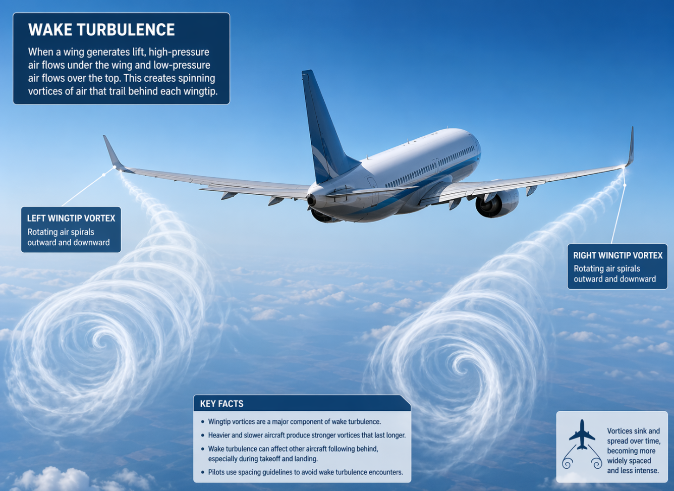
A good advice is if taking of behind an airliner, to wait for at least 3 minutes for the wake turbulence to completely dissipate. Heavy wake turbulence can cause huge problems as the airflow for light planes will be disrupted.
I found a great video explaining the effects of wake turbulence and wingtip vortices here.
Some other facts:
- The strength of the wingtip vortices are caused by the amount of ligt
- The strength of the wingtip vortices are also caused by the angle of attach, where a higher angle of attack will generate more wingtip vortices
- The wingtip vortices are the strongest during take-off and landing
- An aircraft in clean configuration produces the most wingtip vortices
- Wake turbulence will move the direction of the wind
The risks of wake turbulence
The greatest risks of wake-turbulence are:
- Rapid roll-movements which will be so powerful steering against it will not be possible
- Structural damage to the plane
- Loss of height
- Greatly reduced climb performance
- Not enough lift at take-off (if taking of after a HEAVY aircraft)
Wing shapes
The shape of an wing from the top view is called the wing shape. We have mostly two types of wing shapes:
- Straight wings
- Tapered wing
These wings also have some more properties:
- The wing-root is the part which is sticked to the fuselage
- The end part of the wing is called the wingtip
- The wing span is the total length of both wings from the wingtip of the left to the right wing
The distance of the wing leading edge to the trailing edge is called the chord as we already saw. Sometimes this chord is not a straight line. We then speak of a mean chord.
We can calculate the wing aspect-ratio using this formula:
Aspect ratio = Wingspan divided by (/) the mean chord.
Now the aspect ratio also helps producing lift. The higher this ratio, the more steep the lift-curve is. Take a look at this graph:
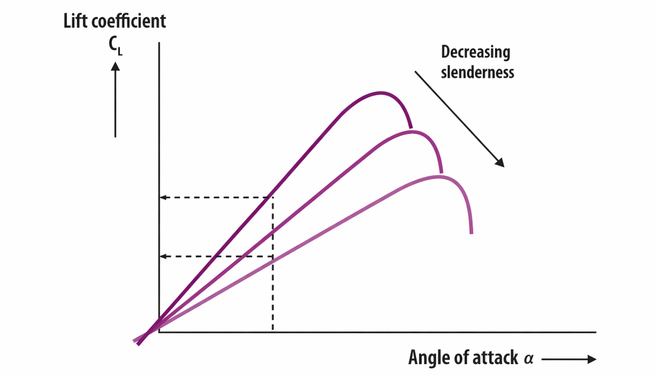
For reference, here a glider plane as a much steeper line than a fighter jet. This is like we already discussed, a result of the wingspan divided by the mean chord.
Wing surface
The wing surface is the total surface area of a wing. We calculate also the part above the fuselage, and is called the gross surface.
Drag (3)
Drag (weerstand) is the resistance of the air a plane flies through. Oncoming wind slams into the cockpit, leading edge wings and wheels and this partly slows us down. More information about this component will be discussed further in this module.
We can feel drag especially when on a bike and going really fast (25-30 km/h or higher). You feel alot of upcoming air which slows you down. This is the exact same on a plane.
To let an aircraft actually fly, the thrust component of the engine must be higher than the total drag at all times. In an horizontal flight, the amount of drag is equal to the amount of thrust, bringing you forward in a constant speed.
The drag formula
The drag formula is similar to the already discussed lift formula, and looks like this:
- Drag = 1/2 ρ V² CD S
| 1/2 ρ V² | CD | Surface |
|---|---|---|
| The dynamic pressure of the incoming airflow (TAS) | Drag Coefficient | The surface of the wing |
The only difference is that we replace the lift coefficient with the drag coefficient. This drag coefficient is also dependent on the angle of attack (AoA). More angle of attack means more drag, as the leading surface of the plane increases a bit.
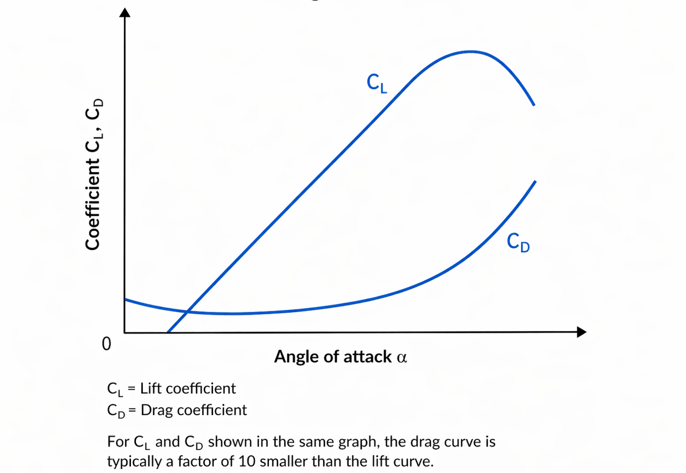
The Drag co-efficient is the sum of Induced drag and Paraside drag combined, which we will discuss further:
Types of drag
We have two types of drag, which we can separate into two categories:
- Induced drag (geinduceerde weerstand): Induced drag is caused by generating lift. When no lift is produced, no induced drag is produced either. We also can call this lift-dependent drag. This drag mostly happens at low speeds.
- Parasite drag (schadelijke weerstand): Parasite drag (schadelijke weerstand) is another type of drag, which increases as the speed increases. We also call this speed-dependent drag. This drag mostly happens at high speeds.
Here again we see the third law of Newton into place; where a specific force is reacted with another opposing force.
Induced drag
So induced drag is produced and a reaction of generating lift. This is caused by the fact that the air over a wing has a lower pressure than under the wing. Because of this pressure difference and high pressure wants to flow to low pressure, some lift will leak away which causes some extra drag.
Induced angle of attack (AoA)
This air can also flow away to the wingtips, which causes some downwash behind the wings. This causes the incoming airflow to get a descending motion and causes the aerodynamic force to tilt somewhat. This also increases the drag component.
We can also have an induced angle of attack where the induced drag is counted from our effective drag.
Induced drag and speed
The induced drag is dependent on the lift as we already stated. The angle of attack also directly impacts this type of drag, where high angles of attack result in more induced drag. The induced drag also increases at low speeds and decreases at high speeds.
- High TAS: low induced drag
- Low TAS: High induced drag
Other factors for Induced drag
Some other factors that can influence the induced drag are:
- Wing aspect ratio: The aspect ratio (ratio between wingspan and mean chord) has a great effect on the induced drag. A thin and long wing (glider) has a short tip and therefore less room for air leakage from under the wing to above the wing.
- Wingtip construction: The construction of the wingtips are also influencing the amount of induced drag. An example is the Beech Bonanza V35 which has somewhat thicker wingtips where some fuel tanks are attached. This reduces the induced drag.
- Ground effect: In the ground effect the aerodynamic properties of a wing will have a minor difference. As there is less air mass just above the ground (0 - 2 meters), there is less room for wing vortices and downwash. This has some profitable results for us: more lift and less drag.
Ground effect
Ground effect gives us more lift, and therefore also a steeper lift coefficient curve. Keep in mind that leaving the ground effect changes the profit back to normal. Ground effect is at its most at a half wingspan above the ground. At 10% of a wingspan, the induced drag will decrease with almost 50%.
We have to take this change in properties into account, especially with landing:
- More lift means a slower descend or even some climbing
- Because of the decreased drag the plane will glide for a longer distance
- The decreased downwash will also decrease the angle of attach of the vertical stabilizer, making the nose descend a little
When taking off, keep this properties into account:
- When climbing out of ground effect, drag increases and lift decreases making us dip a little
- You can rotate with a slightly lower speed but you need ground effect to win speed to get to Vx
- In soft field take-offs you can use the ground effect to eject early from the ground and then win speed in the ground effect
Parasite drag
Parasite drag (schadelijke weerstand) is another type of drag, which increases as the speed increases. This has nothing to do with producing lift.
Parasite drag can be divided into 3 categories:
- Form drag
- Friction-drag
- Interference drag
Form drag
Form drag is caused by the shape/design of the aircraft. As the air flows upon the leading edge, the air will be separated and a pressure difference occurs. By this separation the airflow gets disrupted, building up a new pressure opposing the movement direction. This is called wake.
A brief description is; the more streamlined an aircraft part is, the better the air will follow that part. This will cause less separation and less wake.
A great illustration of this in action:
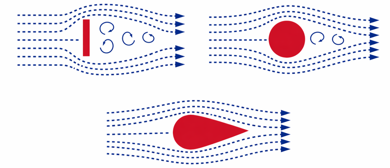
This is the reason planes like the Cessna 172 have wheel-fairings.
Friction drag
When air flows over a fixed surface, air molecules will be braked due to this friction. These slower molecules then will also be slowed down by the molecules farther away from that surface. The further the molecules are away, the less this slowing force is.
Even though air feels light, it sticks slightly to the skin of the aircraft. This creates a thin layer of slowed-down air called the boundary layer. The smoother and cleaner the aircraft surface, the lower the friction drag. Rough surfaces, dirt, ice, rivets, or exposed parts can increase it.
In the cruising phase of a flight, the most drag you feel is an result of the friction drag.
Interference drag
Interference drag is caused by the close placement of all airplane parts close together. All those different parts have their own airflow which can (partly) disrupt each others airflow. This often happens where parts join together, such as the wing and fuselage, struts and wings, or landing gear and body. The airflow becomes more turbulent in these junction areas, which increases drag.
To minimize interference drag, aircraft manufacturers apply fairings to different parts, like from wing to struts.
Total drag
The total drag of that we experience during flights is a sum of induced drag + parasite drag. We can see an example of this put into a graph:
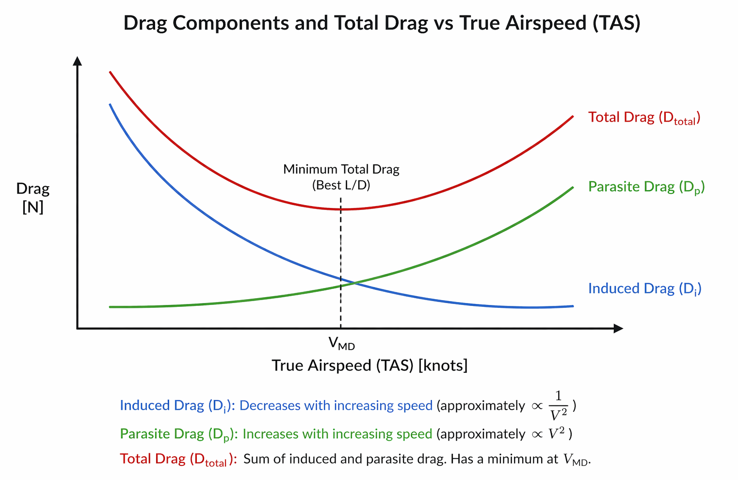
Here we have in the middle a point where we have the least drag, this is where both amounts of drag are exactly the same. This is the V minimum drag (Vmd) speed. Often very similar to our best glide (Vg) speed, used to glide the most distance over a certain amount of distance.
Speed stability of the total drag
We have a graph to get a better understanding of the two parts of drag and your airspeed.
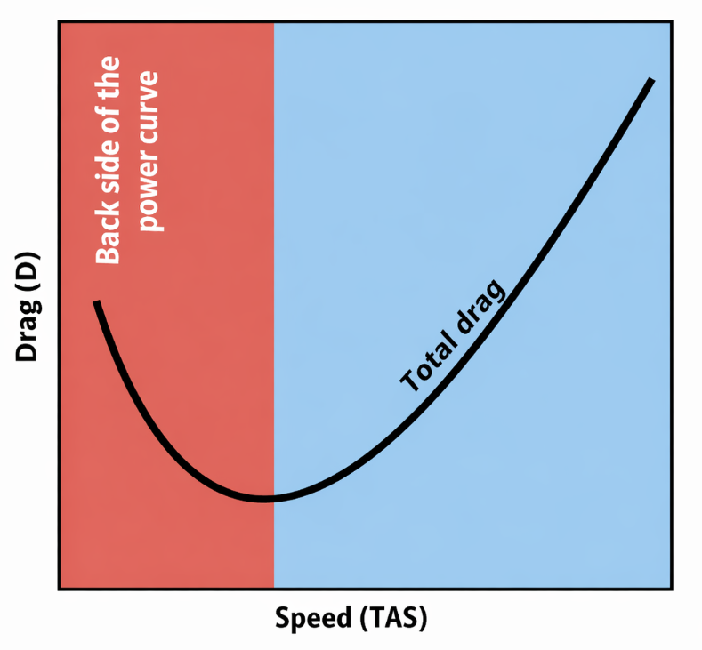
- Red: Backside of the power curve, here is the plane not stable in terms of speed. A small decrease in speed means a increase in drag as the line is steeper. The speed will therefore decrease if not corrected with the throttle.
- Blue: Normal operating area, here the plane is more stable in terms of speed. Light corrections will be applied automatically due to the higher speed.
Stall and spin flight (4)
A stall means exceeding the critical angle of attack. Stalling will occur when the plane has such a high pitch up momentum that the airflow is disrupted. The wing will instantly stop producing lift and the drag will increase substantionally.
Stalling does not neccesarily apply when flying at low speeds. When flying at a low speed, you need to pitch up to retain your altitude. There is a moment that the wings are so high up, causing a wing drop, nose drop or a heavy decrease of altitude occurs. This is a stall. But a plane can also stall when at its top speed, just because the airflow is disrupted.
In aerodynamic terms, we determine the cause of a stalling wing the behaviour of the boundary layer of the wing.
Boundary layer
The boundary layer (grenslaag) is the small layer of air which hits the wing surface. At the surface of the wing, the flow of air will be slowed down as result of resistance. At the surface, the air will even be completely still (no-slip). From the surface the boundary layer will span up to where the flow of air is not disrupted anymore.
A good picture of this happening in both laminar and turbulent air, check out this picture:
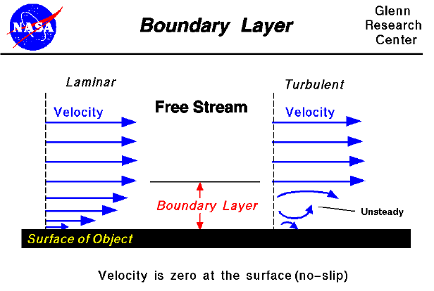
Laminar vs Turbulent
Laminar and Turbulent are each others complete opposites. Laminar beans that the air is very clean (organized) without movement, laminating the air over and under the wings. Turbulent means that this air is very unorganized which can happen by convection (rise of warm air), clean air turbulence or wake turbulence.
When the air is laminar, the following properties are:
- All air molecules will move from left to right
- Nice and orderly
- In parralel lines from each other
Boundary layer separation
When flying at greater angles of attack, the boundary layer will eject from the wing. This separation will result in a loss of lift, and is caused by the pressure gradient from the leading edge of the wing over the top.
From the leading edge of the wing, the pressure drops to a minimum. The point where this minimum is reached is at the front of this wing. After the front the pressure will increase again where at the trailing edge of the wing, the pressure is equal to just before the wing.
After the point of minimum pressure, the boundary layer has to flow in the opposite way, which is not easy by nature. This will increase to happen if the angle of attack also is increases until the wing is in a complete stall. At this stalling point, the separation point has made all its way to the leading edge of the wing.
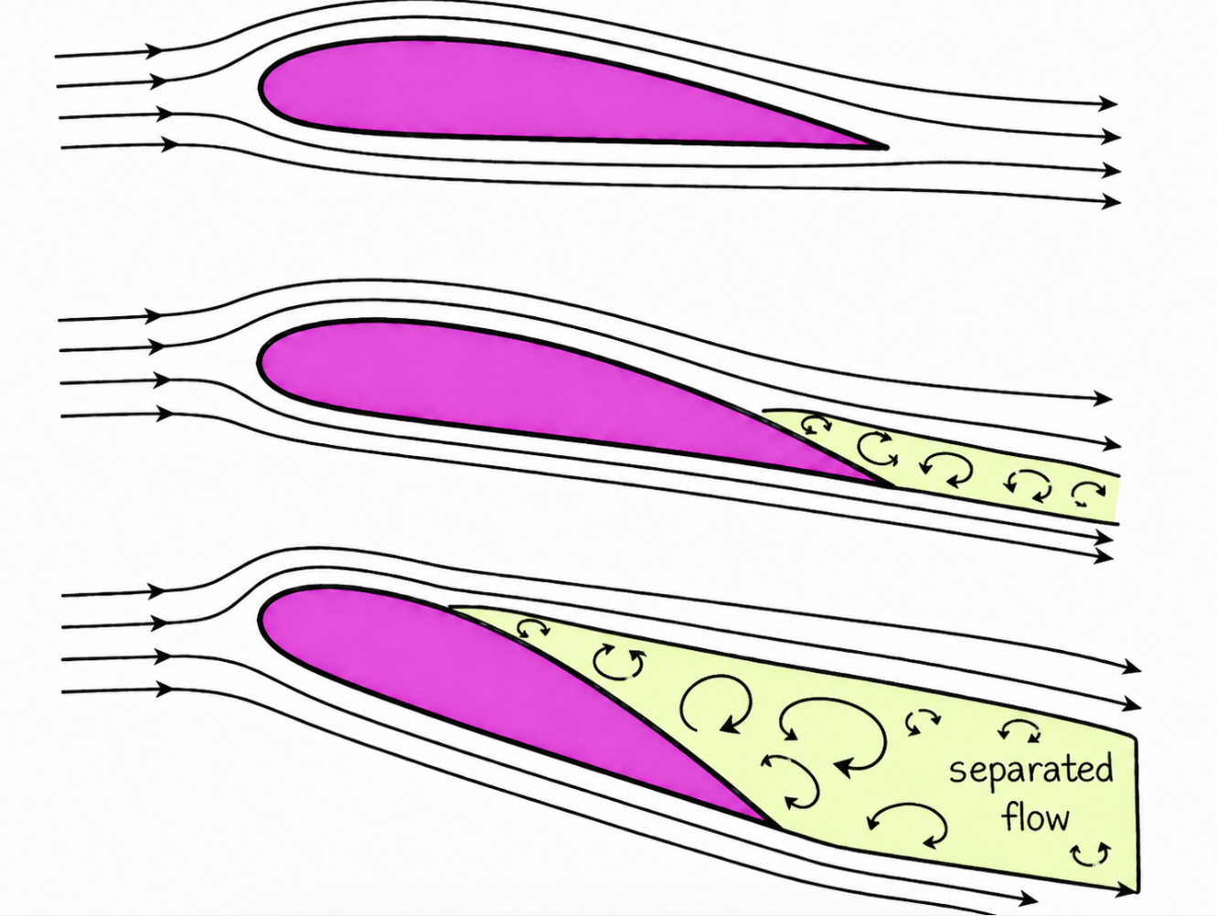
A golf ball has some small dents in its skin. These have a very important cause, namely decreasing the size of the separation layer and so decreasing the total drag of the ball.
Effects of increasing AoA
The effects of increasing the Angle of Attack (AoA) are the following:
- Stagnation point will change to the leading edge -> alerting the artificial stall warning of the Cessna 172
- The static pressure on the top side of the wing decreases
- At a asymmetric wing profile, the rpessure point will change forward to the leading edge at first but at hitting the critical angle back to the trailing edge
- The lift coefficient increases and decreases rapidly after hitting the critical AoA
- The drag coefficient increases slowly but very fast after hitting the critical AoA
- The total drag decreases at a certain angle but increases at a higher AoA
Stall speed
When practicing stalls in a plane, we will close the throttle making the engine run stationary and keep our altitude. We do this because power-off stalls are less dangerous than power-on stalls. As we lose speed, we need to correct for it by increasing the angle of attack. All the way to the critical AoA. In the formula of lift coefficient, the lift-coefficient factor increases where the speed factor decreases.
Just for fun, here is the formula again:
- Lift = 1/2 ρ V² CL S
| 1/2 ρ V² | CL | Surface |
|---|---|---|
| The dynamic pressure of the incoming airflow (TAS) | Lift Coefficient | The surface of the wing |
You can find the stall speed (Vs) in the pilot operating handbook (POH) of the plane. V speeds are always referenced at the Indicated Airspeed (IAS), which is what you see on your speed meter in the cockpit.
For more information about stalls and my stalls lessons, visit this page:
Stall speed factors
There are some factors that influence the stall speed of the plane. Because the speed is not a hard value, especially in the atmosphere which can change from time to time, they are all calculated using the following properties and are worst case scenarios:
- No flaps: Flaps help reducing the stall speed by around 5 knots on a Cessna 172
- Straight and level horizontal flight
- No engine power
- Center of gravity is in the front position
- The plane is at its maximum take-off weight (MTOW)
Weight
According to the lift formula, the lift factor must be equal to the weight factor to stay in the air. The lift factor must be higher if you want to climb. The POH always refers to the maximum take-off weight, so the worst case scenario here.
Womething which also is an option is to look at the ratio between weight and wing surface, which we call the wing loading:
- Weight/Surface = 1/2 ρ V² CL
How more the wing loading factor is, the more the stall speed.
Load factor
The load factor is the ratio between lift and weight. We will pronounce this in simple numbers: in straight and level flight, this ratio is 1. When manoeuvering, like turns or climbing this ratio will increase. At an angle of 60 degrees while climbing the load factor will be 2.
We can make this load factor visible with a little addition to the lift formula:
- Load factor x Weight = Lift = 1/2 ρ V² CL S
Here is described that the lift must not only be equal to the weight, but on the weight multiplied by the load factor. This makes clear that a change to the load factor has the same effect as on weight increase of difference.
For reference, here we have some numbers where we describe the load factor and increase of stall speeds in different turns:
| Load factor | 1 | 1,15 | 1,4 | 2 | 3,9 |
|---|---|---|---|---|---|
| Increase in stall speed | 0% | 7,5% | 19% | 41% | 97% |
Fun fact, the load factor is equal to the G-force.
Thrust
The thrust is the forward power the engine(s) and propellor(s) generates and will influence the stall speed in two ways:
- Thrust increases the vertical power/component
- Thrust increases the airspeed over the wings
At higher angles of attack, the thrust gets a upward component. The thrust reduces somewhat of the weight, where the lift decreases without stalling. The stall speed will get somewhat lower because of this when having full engine power.
Extra thrust on the propellor will also increase the flow of air over the inside - parts of the wings. The inside parts of the wings will get more air decreasing the stall factor there. This is great, as we keep control over the ailerons. However, when stalling, you must only steer with the rudder to avoid a spiral dive/spin.
Center of gravity
Another factor on the stall speed is the center of gravity. Ever tried to balance a straw on your finger? The point where the straw stays into plane without tilting to one of the sides is called the center of gravity.
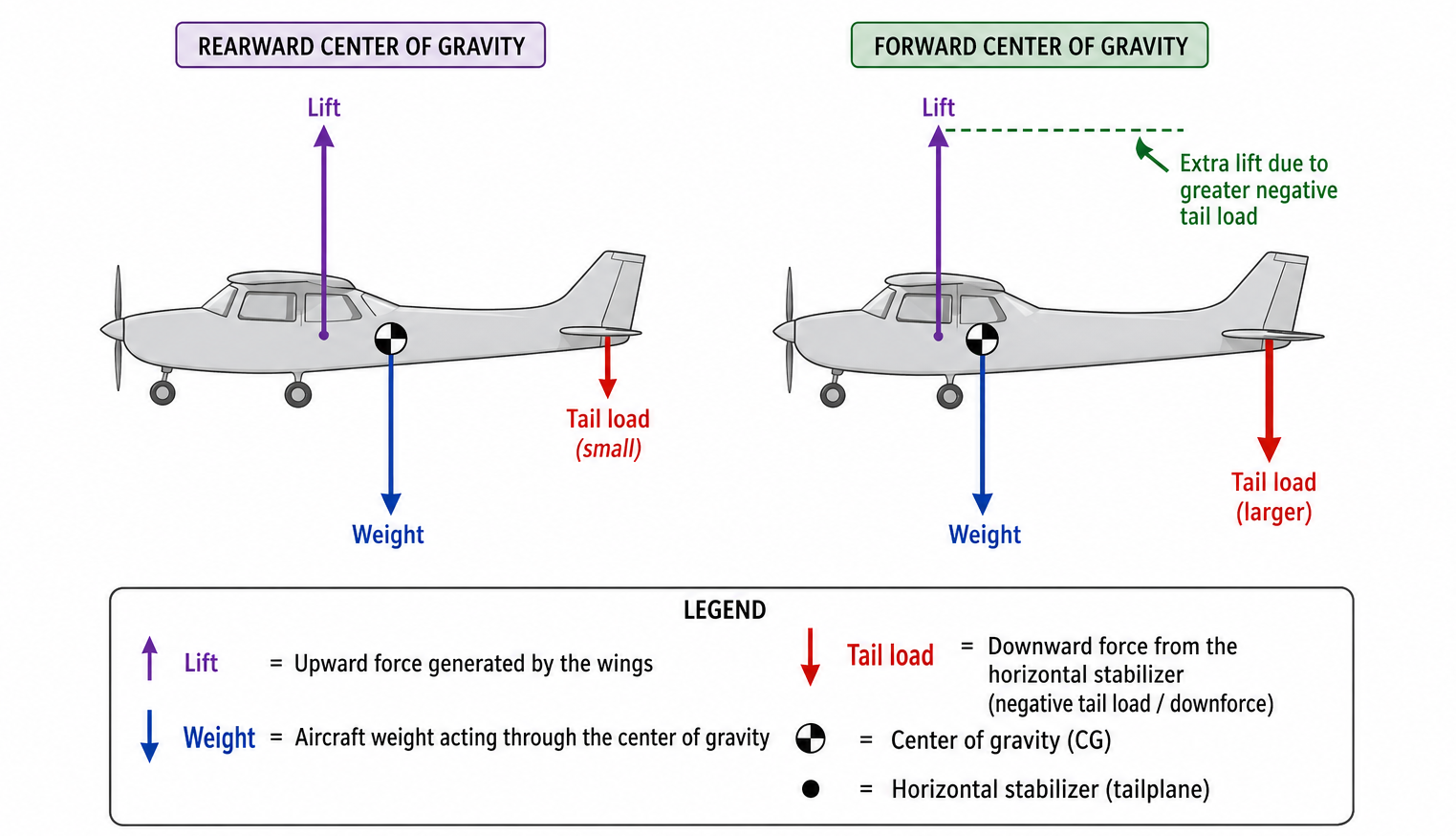
In a plane we have also a center of gravity as we must be in balance. If the center of gravity is at the front section of the fuselage, the stall speed will increase. This is due to the extra correction the horizontal stabilizer needs to make to keep the plane level and this increases the stall speed. The POH refers to the most forward center of gravity possible while still inside of the Mass and Balance envelope as worst case scenario.
Turbulence
Turbulence is also a factor which can influence the stall speed. In turbulent weather, the wind speed and direction will constantly change. This results in a angle of attack which also changes in small differences. At low speeds with high angles of attack, a upward wind can pull the plane into the critical angle of attack, resulting in a stall.
Stalls in climbing or descending turns
When climbing or descending, the wings have both a different angle of attack. This difference occurs because the outside wing has a longer distance than the inside wing. Because both wings are vertically making the same distance, the flight path of the outside wing has a flattened curve.
In a climbing turn, the angle of attack of the outside wing is the highest. If the speed decreases, the outside wing will stall first. At a descending turn, the inside will stall first. This is the reason the turn from base to final in the circuit is the most dangerous turn, which is commonly flown with somewhat more speed and a less steep turn (around 20 degrees in a Cessna 172).
While climbing:
- Outside wing stalls first
While descending:
- Inside wing stalls first
Stall warning
When an aircraft is in a stall, the plane will lose altitude very fast and the plane can become uncontrollable. A stall warning is therefore very important, as this can (re)gain your attention. The stall warning sounds just before a real stall happens, giving you enough time to remediate the risk instead of fixing the stall.
We call it an approach to stall when a stall is around the corner but not fully developed. You can see this as the point in the lift coefficient curve where the line stops to increase.
Sympthoms of an approach to stall are:
- Stall warning horn rings
- Buffeting, this is an aerodynamic clue that the plane is about to stall where the drag of the separation layer takes over the lift making the aircraft shake somewhat
- This effect is not that audible on a Cessna 172
- It does on low-wing aircraft like Piper, Diamond Aircraft or Cirrus types
- Airspeed too low
- Controls becoming sloppy -> lower airspeed means lower air and less “grip”
We have two types of stall warnings on general aviation aircraft:
- Electrical flapper
- Underpressure horn
Both systems relatively work the same, where both will sound an alarm if the stagnation point will shift more to the underside of the leading edge because of the critical AoA. The electrical flapper works on electricity and is more or less a button which must be pressed up. Is the button pressed, then the alarm will sound. The underpressure horn is mechanical and works at all times, by sounding the alarm if air is sucked through it.
These alarms will sound in normal conditions, at around 5 to 10 knots prior to hitting the critical AoA. However, if dealing with ice build up on the wing, the wing will already stall before the alarm is sounded which makes this situation very dangerous. For more information about ice build-up, check out: the meteorology page.
Flight properties at a stall
A nearing stall has some downsides to the controls of the plane. If one of the wings will stall prior to the other, then this will result in a wing dip and also in a spral dive if not corrected. To help pilots with controlling a plane that is about to stall, aircraft manufacturers have some design improvements done to the wings.
- Washout: Sometimes a wing is somewhat twisted by design, where the angle of incidation at the root is bigger than on the tip. This causes the root to stall first leaving enough air to still control the aileron at the tip. This difference is mostly some degrees. This also creates that buffet effect on the stabilo where a pilot is alerted about a nearing stall without any electrical or mechincal parts working
- Stall strip: This is a metal strip on the leading edge of the wing which also causes the wing root to stall earlier than the tip.
Stall prevention and recovery
As we already discussed, a stall is caused by exceeding the critical AoA. To recover the stall, we need to minimize the AoA and so need to push the yoke forward.
An aircraft has also some features to recover itself aerodynamically:
- Backward movement of the pressure point
- Decreasing the AoA of the stabilo
The stabilo always has a smaller AoA than the wings. This is by design, so the pilot has elevator authority even at a stall of the wings. If the plane stops pitching up, the downwash of the wings will reduce also resulting in the stabilo to decrease its AoA.
Ice build up
Ice can build up on the plane on the ground and during flight, when the air is saturated enough and also under the freezing point. If having ice on the wings and you are still on the ground, do not take-off.
Ice will build up on mostly the leading edges of the wings, horizontal and vertical stabilizer and on smaller parts like the pitot tube and antennas. Even a small layer of ice can reduce lift by up to 50% and increasing drag by up to 100%. This because the friction drag is increases and this will influence the boundary layer.
In short, no flights if having ice on the plane.
Spins
During a stall the plane can roll. This roll movement can have different causes like propellor slipstream, turbulence or minor differences in the wings or plane shape.
Because of the roll movements the AoA of the descending wing will increase. As the wing is already stalled the lift will decrease with the result the roll movement will be enhanced and another decrease of lift. When in a stall, roll movements will not be silenced like in normal flight. This roll momement is called a wing dip.
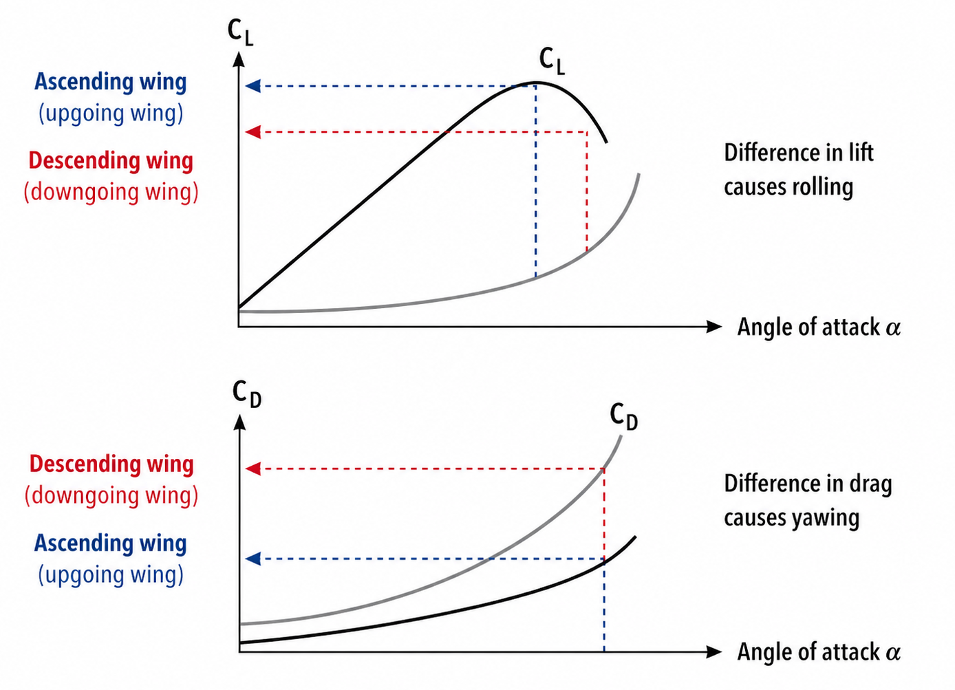
A plane has some side-effects when controlling. If steering with the yoke to roll, some yaw is a side effect. If controlling the rudder to yaw, then rolling is a side effect because of the differences in drag and lift.
In a spin these movements will stay and this situation is called autorotation. The result of this is a downward spin flight or in short a spin.
Phases of a spin
The spin can be divided into three phases:
- Wing dip: One of the wings dip because of a stall
- Incipient spin: This is the first 1 to 3 rotations where the nose also dips and a spin is imminent if not corrected by the pilot
- Developed spin: Here the plane has all its momentum to keep spinning, the airspeed looks low that this phase but the descending speed is very high
Spin recovery procedures
We can recover from spins safely if we have the altitude:
Recovery from wing dip
- Opposite rudder to level off the plane
- Unload the wings by pushing the yoke forward
- Level off using the yoke
Recovery from fully developed spin
- Close the throttle to not be sucked into the spin, this decreases aerodynamic forces on the plane
- Ailerons neutral, keep them level
- Full opposite rudder as your spin direction
- Steer level
- If the spin has stopped stop rudder input and pull out of the dive
As we already saw in the flight lessons of stalls, we must never use ailerons to get out of a stall. This makes a difference in the AoA of the ailerons making the situation even worse.
Spiral dive
A spiral dive looks similar to a spin but in a spiral dive there is no stall active. In a spiral dive the AoA is small at a high and increasing speed.
The spiral dive can occur when making a steep turn of 45 degrees or more to correct for a low pitch by pulling on the yoke. The nose will hardly rise and the turn will be tighter causing the nose to drop even more. The speed will increase in this situation.
To recover from a spiral dive:
- Close the throttle to not be sucked into the spin, this decreases aerodynamic forces on the plane
- Level the plane with the ailerons -> because of the high airspeed you have a lot of aileron authority because of the loads of air
- Pull up from the dive
Aircraft Controls (5)
The movements of an aircraft can be defined using these three imaginary axis':
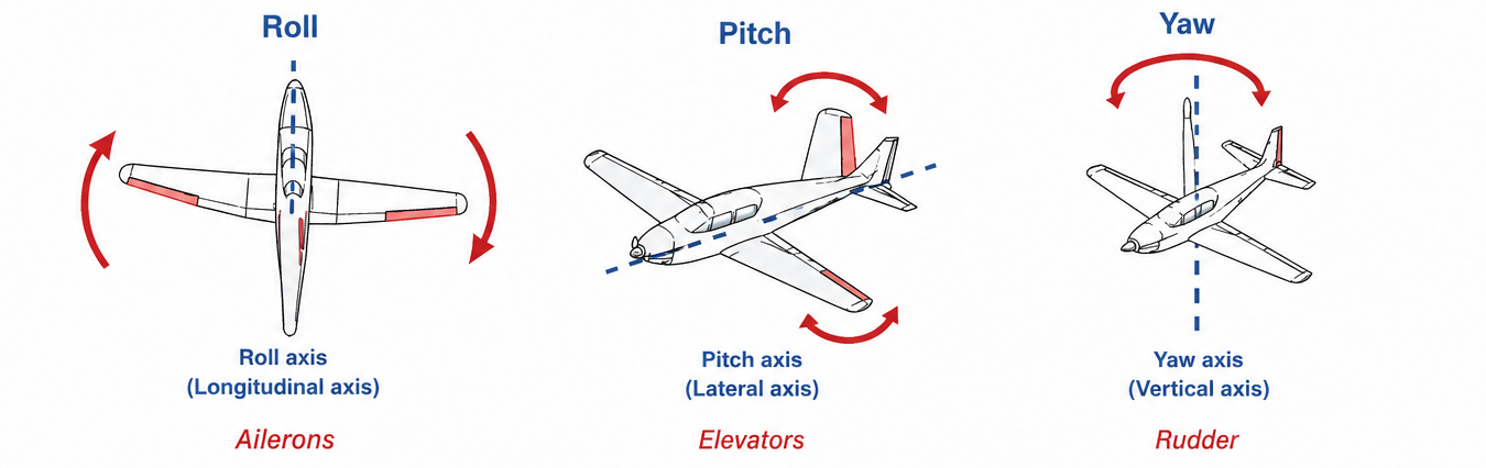
All these axis’ come together at the center of gravity of the plane. To put all effects and controls in a table including the dutch translations:
| Axis | Axis (dutch) | Effects | Effects (dutch) |
|---|---|---|---|
| Longitudinal axis | Langsas | Roll | Rollen |
| Vertical axis | Topas | Yaw | Gieren |
| Lateral axis | Dwarsas | Pitch | Stampen |
Primary Flight Controls
These effects and axis’ are primarily controlled by the primary flight controls:
- Roll: Ailerons
- Yaw: Rudder
- Pitch: Elevator
All of these controls work similar. They change the camber (welving) of the wing or elevator. One of those controls in downward position means an increase of lift, where a upward position means a decrease of lift. It just changes how the air flows around.
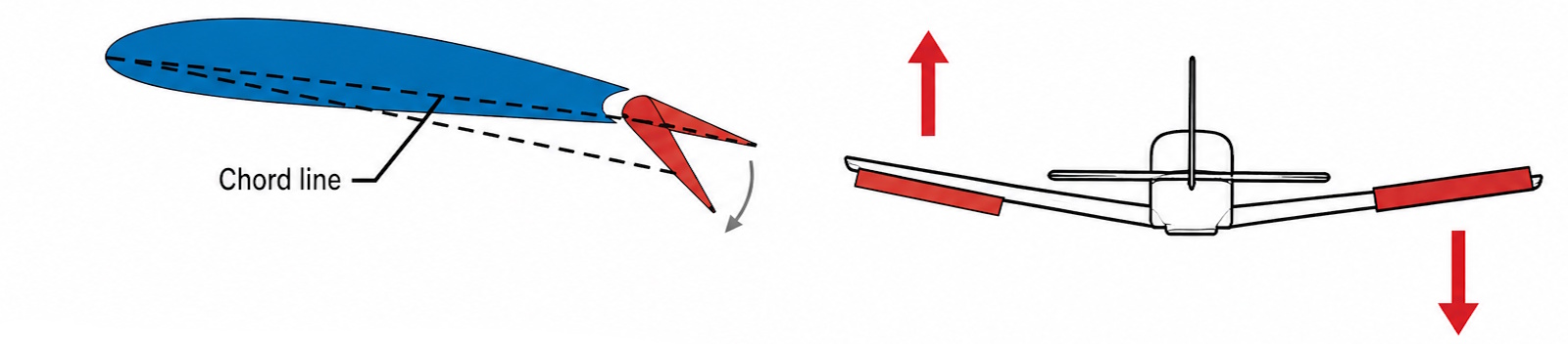
If we look at the ailerons, we can see that they also change the wing’s angle of attack. As a result, the chord line tilts slightly, causing the aircraft to roll. On most aircraft, the ailerons are located near the tips of the wings. This is related to the moment arm: the farther they are from the fuselage, the less control force is needed to produce the rolling motion.
Side effects
- Rolling is yawing
- Yawing is rolling
These controls are not completely separated from each other. For example, if we only steer with the rudder, the plane will also roll. This is because the outside wing will produce more lift as result of the higher speed. A rolling effect will be felt and seen.
The other way around, if we only steer using the ailerons, then we can feel also a yawing motion. This is an result of the lift which now works from an angle. The incoming airflow hits the horizontal stabilizer under an angle getting a side-aerodynamic force resulting in a yaw towards the low wing.
The plane wants to get the nose into the wind. This is what we call the weathercock effect.
Hook effect
During a rolling movement the aileron of the upward wing will move down to create more lift. This also results in more drag. This extra drag results in the plane to yaw in that direction which is called the hook effect.
To help reduce this hook effect, aircraft manufacturers apply these design-additions to the ailerons:
- Differential ailerons: Here the movements of the ailerons are not in sync. The upward aileron had a bigger movement than the downward aileron. This gives both wings an equal amount of drag suppressing this effect greatly.
- Frise ailerons: These are constructed so the leading edge of the aileron will get some incoming air under the wing. This also gives both wings an equal amount of drag suppressing this effect greatly.
The remaining effect can be adjusted by steering with your rudder. This is what we do in the cockpits.
Effects on controls and airspeed
When the control surfaces (roeren) have more airspeed, the effectiveness (which we call authority) increases. As more air passes by over the control surfaces, it has more to make their movements. This is the same reason as why on lower speeds you need to do bigger steering actions.
The elevator and rudders exist in the slipstream of the propellor, so the effectiveness of these tail controls are also dependent on the engine RPM. Not only the airspeed, as on higher RPMs the propellor rotates a lot faster.
Influence of Engine RPM on pitch
The engine RPM also has influence on the effectiveness of the stabilizer controls. More RPM means a faster slipstream and a increase in downwash behind the horizontal stabilizer. If you increase RPM, the horizontal stabilizer will be pushed downward which increases the nose pitch. Decreasing RPM does the complete opposite, lowering the nose and increasing the horizontal stabilizer.
This is a design requirement for all planes; the nose must be going down after decreasing engine RPM to hold a specific speed. This prevents a unpredicted stall.
Mass balancing
The construction of an aircraft has a good flexibility and can deflect some during aerodynamic forces. If a wing bends downward because of turbulence, the aileron will be somewhat behind because of mass slowness and results in the wing pushed even further downward.
In the process of mass balancing, sometimes there are placed some small parts of metal in various places on the plane to ensure both sites are of equal weight. This decreases things like flutter which is an aerodynamic unbalance and can break an aircraft in seconds. This is always done in the section before the Vne speed, which is the Never Exceed Speed (160+ knots on a Cessna 172).
Aerodynamic balancing
Any of the control surfaces will pick an attitude which is level with the incoming airflow. To actually steer an aircraft, the pilot must win this incoming airflow by putting more force into the controls. In the factory, aircraft manufacturers apply some tricks on the airplanes to keep the controls into balance. One of the things on a Cessna 172 to achieve this aerodynamic balance in the controls is a horn balance. This is this part of the elevator:
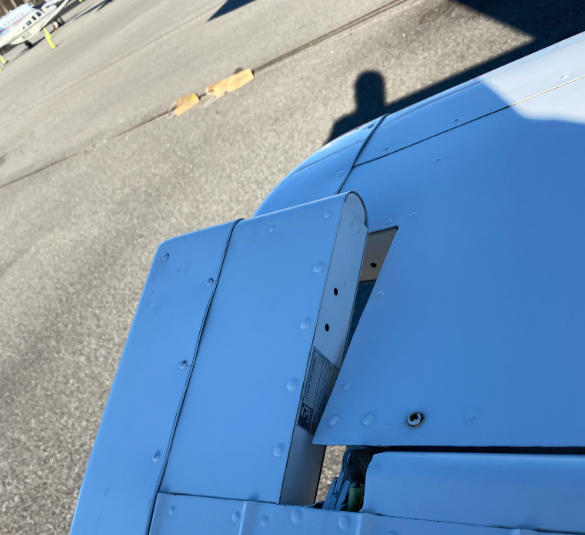
Aerodynamic balance can be seen as powered steering in cars. They make the steering process a bit better, decreasing the change of flutter.
Trim surfaces
A plane also has some trim surfaces which are mostly controlled using a trim wheel in the cockpit The movements of this wheel corresponds with the movement of the yoke.
These are two types of adjustable parts of control surfaces to further enhance flights:
- Adjustable trimming surfaces: These can be adjusted during flight to keep a plane straight and level
- Balancing trimming surfaces: These can only be adjusted on the ground and mostly by the aircraft manufacturer
Trimming surfaces are so small parts of moveable control surfaces at the end of that surface. These can be set in a specific way, so the pilot doesnt need to apply forces on the yoke at all times.
For example, the Cessna 172 has a adjustable trim surface on the elevator. With this surface, we have a small part of the big elevator which can be controlled to stay in a desired position. This only controls the pitch axis.
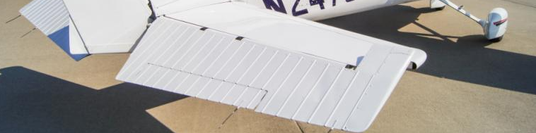
This small part changes the camber of the elevator, where the elevator surface controls the camber of the horizontal stabilizer itself. By setting the trim there will be some camber at the backside of the elevator. This small setting is enough to keep the elevator in a fixed position. All of this is done using aerodynamic forces, so that is the reason the position of this trim is completely the opposite of the elevator itself. At take-off we set this small surface level with the elevator.
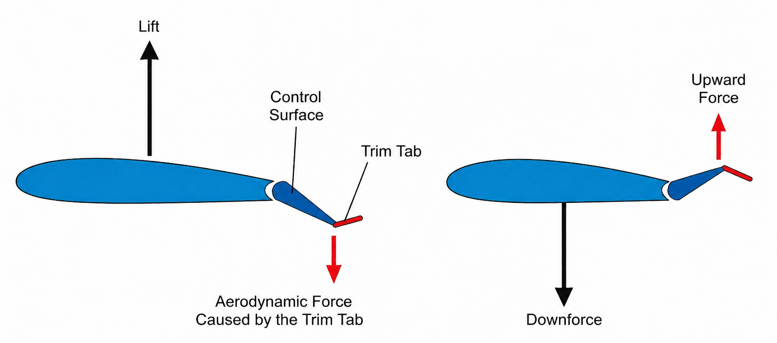
This trim in a Cessna 172 is controlled using a trim wheel in the cockpit.
Ground adjustable trims
A plane sometimes also has some ground adjustable trims, like the bottom corner of the rudder. If the plane has a few grams offset, these can be bent to make them aerodynamically stable.
Some planes also have balance-surfaces which reduce the force needed to steer the aircraft. This is the complete opposite of the trim, where the balance surface does exactly what the elevator itself does, sometimes even with a bigger steering effect.
Flaps
Flaperons (kleppen) are meant to alter the flying properties at lower speeds. These are surfaces at the trailing edge of the wings. They work basically by changing the camber of the wing somewhat, where they increase lift and drag. This makes flying at lower speeds possible during take-offs and landings.
Flaps are often mechanically or electrically and are measured in how much degrees difference they offset from the angle of incidation of the wing.
Flaps have some pro’s in using them:
- The lift coefficient shift up and somewhat to the left, making the stall speed lower
- The critical AoA increases a little with flaps extended, this is because of the extra drag
- Flaps increase drag, and slows the aircraft down
- Flaps help to see the runway much better during landings as the AoA is lower
- The stagnation point of the wing shifts somewhat backwards
Types of flaps
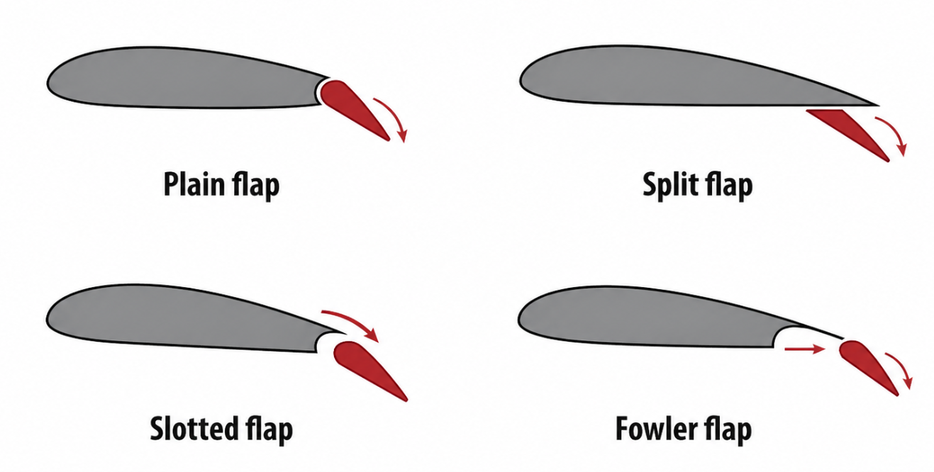
Historically multiple types of flaps has been tested and the most used types are these:
- Plain flaps : Mostly used on weight reduced planes like bush planes and is a plain part that pushes downwards
- Split flaps : Old technique where the trailing edge of the wing actually splits. The legendary DC-3 has them for example
- Slotted flaps : Similar to a plain flap but incorporates a gap between the flap and the wing to force high pressure air from below the wing over the upper surface of the flap. Used on most general aviation aircraft like Cessna 172
- Fowler flaps : Extended out of the wing and pushed downward. Used the most on traffic jets (A320/A330/A350, B737, B777, B787)
Operational use of flaps
We generally use flaps in the take-off and landing phases of flight where these have advantages.
During take-offs
- Decrease of ground roll
- Increase in lift, slight increase of drag
After taking off, we set them very fast to 0 as because of the increased drag, we will achieve lower speeds.
During landings
- Decrease of stall speed
- Lower pitch attitude
- Steeper approach and better obstacle clearance
- Higher drag means a better round out above the runway
Leading edge flaps (Slats)
Slats have the exact same purpose as flaps, increasing the lift coefficient making lower speeds possible. They are installed on the leading edge of the wings instead of on the trailing edge. They are always combined with flaps settings to prevent any assymmetry from happening.
Slats also help increasing the critical AoA where flaps only decrease them but help to fly at lower speeds. Slats are mostly used on bigger commercial jets and bigger general aviation aircraft.
Turning
According to Newton’s first law, an object without any forces will move in a straight line with a certain speed. Making a turn thus needs a net force. The net force on an object is the sum of all forces acting on it.
“An object at rest stays at rest, and an object in motion stays in motion at a constant velocity, unless acted upon by a net external force.”
This force will work right onto the movement direction of an airplane and because every turn will be part of a circular movement, the required force will point to the middle of the circle. This force is called the centripetal force (middelpuntzoekende kracht).
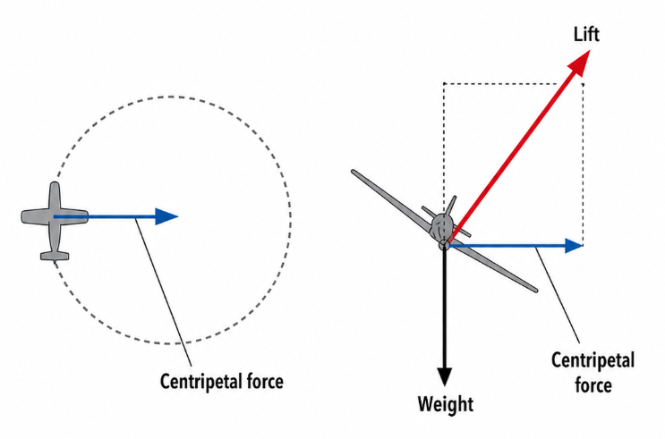
This centripetal force is a result of the horizontal component of the lift which occurs when the plane banks into a turn.
Balance of force in turns
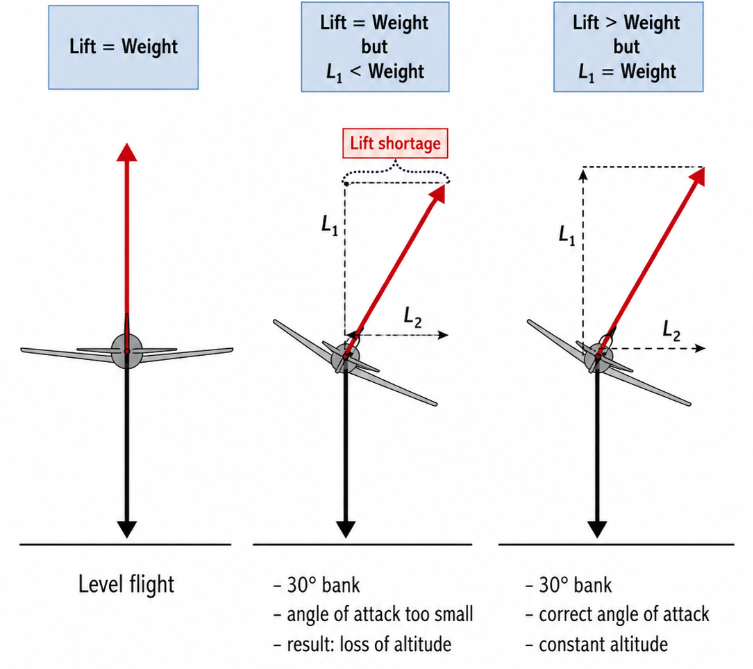
If a plane turns in an incorrect manner, there will occur a situation where there is no balance between the vertical forces. The gravity will stay in a straight line to the earths surface but the vertical component of the lift is tilted (to the turning side) because of the turn. This vertical lift component is now smaller than the gravity, making the plane go down. This is why a plane needs some back pressure on the yoke in turns, which increases some lift to compensate and recover the balance between lift and weight.
To get a better view of this occurence:
Rate of turns
The speed of how we fly a turn is called the “rate-of-turn”. This is measured in the amount of degrees change per second. The most important one is a Rate one turn which is 3 degrees per second and costs 2 minutes for a full circle. You can calculate the amount of degrees needed to bank with this formula:
- Bank angle for rate one = TAS in knots : 10 + 5
As we can see, the airspeed is a dependency on the bank angle. Let’s say, we fly at 135 knots and want to make a rate one turn:
- 135 : 10 + 5 = 18,5 degrees bank angle
Some other examples:
- Cessna 172: 95 : 10 + 5 = 14,5 degrees bank angle
- Airbus A320: 235 : 10 + 5 = 28,5 degrees bank angle
The fun fact is, the only two dependencies are the airspeed and the bank angle. If you want to fly a turn slower, decrease your airspeed. If you want to complete a full circle faster or in a more narrow area, increase the bank angle.
Turn coordination
During a turn there will be some yawing motion. The nose will also turn in the direction of bank. If the yaw-speed is correctly and in sync with the bank angle we speak of a coordinated turn. A situation where the incoming airflow is coming straight from the front, seen from the cockpit.
If this is not the case, we have two other options:
- Slipping turn: The nose falls behind when not enough rudder input is given
- Skidding turn: The nose is in front when giving too much rudder input
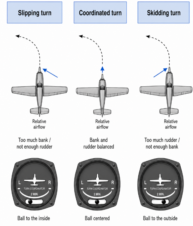
In the cockpit we have the turn coordinator which works with a gyro, telling us exactly how much rudder input the plane needs. The keyword here is: “Step on the ball”, meaning to press the pedal at the side of the ball just to keep it in the middle.
Load factor during maneuvers (6)
The construction of an aircraft needs to be solid enough to catch all forces, both on the ground and in the air. The aircraft parts need to be strong enough to carry its weight on the ground, especially at harder landings. In the air, the plane also needs to be strong enough to withstand some maneuvers like:
- Turns
- Turbulence
- Dive flights (aerobatics)
During the design of an aircraft, manufacturers takes the expected load factors into account. The load that an aerobatic plane gets is of course much higher than a Cessna 172. Under static strength of an aircraft we think of the force or load the construction can have once without breaking. If an aircraft is under load for multiple times there can happen some metal fatigue, permanently weaken the construction. During the walk around, this is one of the visually things to check on an aircraft:
- Cracks
- Wrinkled paint job
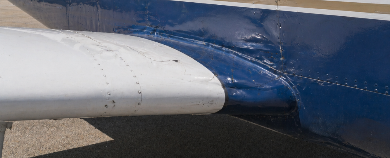
The maximum load factor which the plane must withstand is called the limit load. This possible load factor number is the force a plane with an undamaged construction can have. Under this number, some part smay temporarily bend like the wings but the flight properties may not be influenced.
Load factor numbers
The static strength of an aircraft is measured in G-force, where a plane on the ground is always 1G, or 1x the mass.
Again, here we have some numbers where we describe the load factor and increase of stall speeds in different turns:
| Load factor | 1 | 1,15 | 1,4 | 2 | 3,9 |
|---|---|---|---|---|---|
| Increase in stall speed | 0% | 7,5% | 19% | 41% | 97% |
Now we have some extra numbers for different category airplanes:
| Category | Positive load | Negative load |
|---|---|---|
| Normal | + 3,8 G | - 1,52 G |
| Utility | + 4,4 G | - 1,76 G |
| Aerobatic | + 6,0 G | - 3,00 G |
Always refer to your planes POH for the actual numbers, the numbers above are generally for aircraft categories. Different planes are certified for different amount of forces.
G force factors
Planes are mostly designed to carry positive lift, so the positive G force numbers are higher than the negative numbers. During negative G forces, all parts are loaded downward but planes are actually designed to fly upward.
The Load factor diagram
The load factor diagram shows at which speeds a specific aerodynamic load is pushed on the plane. The load factor as we already know is a ration between lift and weight so these numbers influence the load factor. To be careful enough we need to take both numbers into account.
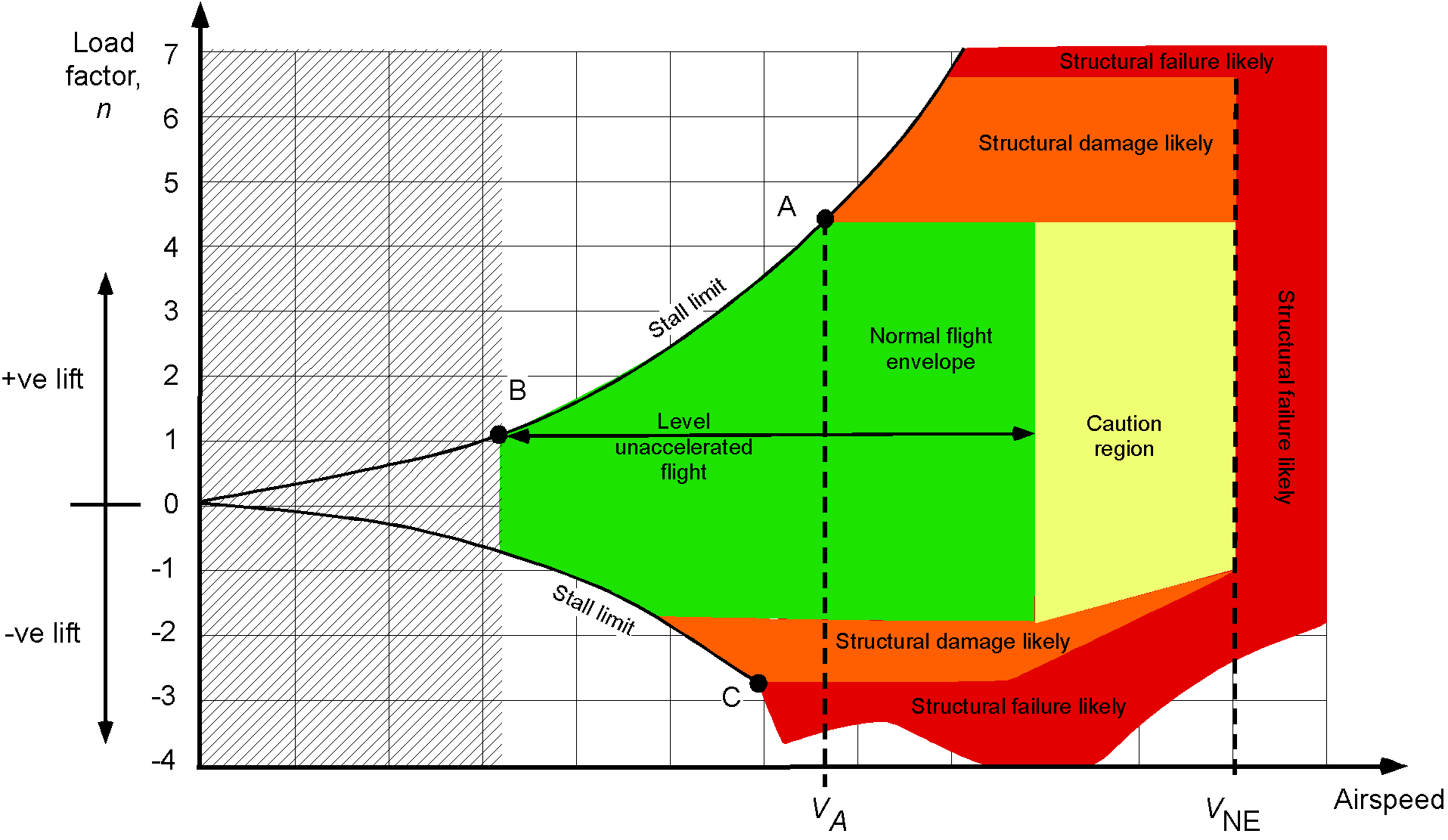
At higher speeds we can produce more lift, so the lift number goes up at higher speeds. The Va speed is the maneuvering speed of an aircraft, which is around 103 knots in a Cessna 172. This is the speed where full inputs can be given to the plane without overstressing the plane. The Vne speed is the Never Exceed speed and is the red line on the airspeed indicator.
The non colored parts of the graph are outside the stall limits no are aerodynamically not reachable. As you can see is the most change of overloading the aircraft at higher speeds.
When a plane flies at 87 knots for example, a pull on the yoke will result in the plane first loaded to 2G and then in a stall as it comes outside of the green area. At an speed of 120 knots and higher with a Cessna 172 its possible to reach the limit load factor. But this can be reached earlier in the envelope if the plane has more weight. This is described by the second law of Newton: “The acceleration of an object depends on the net force acting on it and the mass of the object.”
Aerodynamics of propellors (7)
Obviously the job of the propellor is to convert engine power into thrust. Thrust is forward power of the plane which also can be helpful turing climbs. The propellor of the plane is directly connected to the crank-shaft (krukas) or indirectly with a gearbox.
Most planes in general aviation have 2 to 4 propellor blades and can contain up to 7 in some cases, but 2 to 4 are the most generic options. The blades are often made of aluminum or carbon fiber and meet each other at the hub, where the propellor is connected to the crank-shaft. The part on top of the propellor is called the spinner, which makes the propellor aerodynamically streamlined.
Propellors of a fixed pitch propellor plane are often twisted at the center. This is done to make the AoA of the propellor in the incoming air the same for the whole blade. The center part gets less air, so get a higher AoA. Exactly the same principle as the wing and the flaps as we already know. This is called propellor wrong.
The spinner is streamlined for better aerodynamic performance but also is used to steer air into the air-inlets to cool the engine. Very clever designing.
How a propellor works
The propellor works almost the same as a wing. They also have incoming air and the blades making an AoA relative to the incoming airflow. The propellor then causes a resulting air force. This force can be divided into:
- Thrust: Straight and forward power
- Drag: Drag of the propellor
- Resultant aerodynamic force: The two forces of forward and drag means a resulting force that is somewhere between those two axis, totally dependent on the pitch of the nose
Propellor blade angle
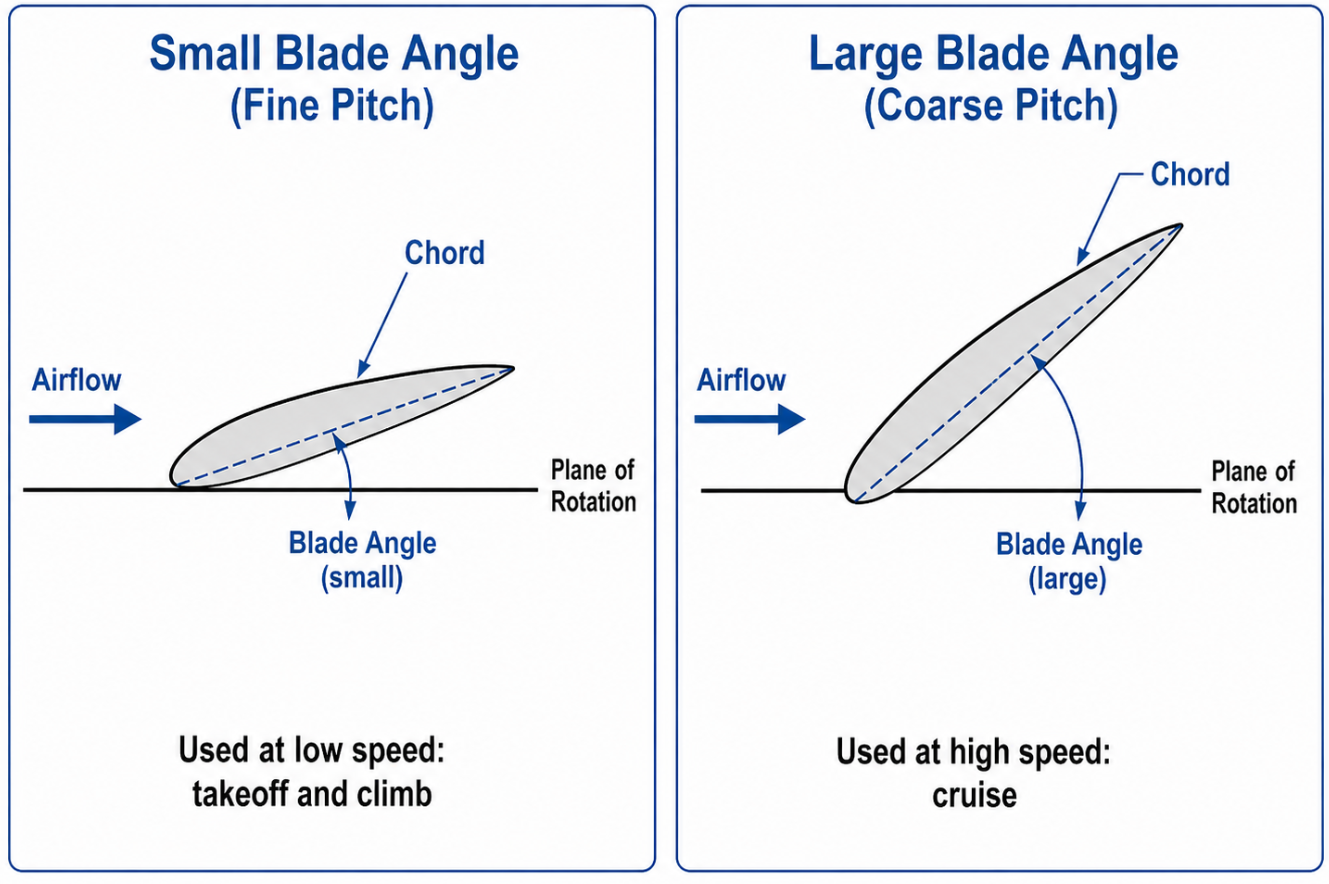
The blade angle of a propellor is the angle between rotation-axis and the chord of the blade. The pitch of the propellor (spoed in Dutch) is the theoretical distance the propellor covers in one rotation:
- Small blade angle: Fine pitch -> Optimal for climbing
- Big blade angle: Coarse pitch -> Optimal for cruise
The blade angle of a propellor is similar to the angle of incidence on a wing.
Propellor Angle of attack
The angle of attach of a propellor blade is the angle between chord and incoming air. Just like a wing. A plane who is standing still on the ground, the AoA is equal to the blade angle as there is not that much incoming air. If the plane moves forward, more air will come in from the front. The angle of attack decreases in this case.
At an increasing forward movement speed the AoA will be 0 or even negative. The propellor doesn’t produce thrust anymore.
Propellor Wrong
The propellors of fixed pitch propellor planes like the Cessna 172 are slightly wronged. This means the root of the propellor has a bigger AoA than the tips. As the whole propellor rotates, the tip will cover a much bigger distance than the root of the propellor. This results in less air picked up. To compensate for that effect, the AoA is higher at the root of the propellor to span the thrust over the whole blade. If these are not wronged then the propellor will be working very inefficiently.
Fixed pitch propellor RPM
In fixed pitch propellor planes like the Cessna 172, the RPM of the engine is equal to the RPM of the propellor. The AoA of an propellor is the highest when standing still on the ground. At a high AoA, the drag is also much bigger making full throttle exercises not very dangerous for the engine.
When flying the propellor produces forward motion (thrust) the AoA will decrease. This also results in a lower drag making the propellor spin slightly higher. Theoretically you can’t exceed the engine rpm limits on the ground, only in the air because of this. This phenomenon is also to be seen during flights. When the pitch attitude is higher, the engine RPM will decrease. When descending, the RPM will decrease. During descends we also draw the power back. The much lower drag and the extra downward thrust you otherwise get can reach high speeds in seconds.
Propellor windmilling
When the forward speed increases, the AoA of the propellor will decrease. At a certain rotating speed the AoA becomes zero and no thrust will be produced by the propellor at that point. If the speed increases even more than that, the propellor AoA will be negative; the propellor produces drag instead of thrust.
The propellor stays rotating because of the incoming airflow, making it a flying windmill. At an engine failure, the propellor will also continue to rotate. This windmilling effect causes some more drag. This extra windmilling decreases the glide angle and so gives you less gliding distance.
Engine power to thrust conversion
The power a propellor gives is dependent of the forward speed. Power x speed. If a plane is standing still with a rotating propellor, trust is produced but the power is 0. At an increasing forward speed the power is also increasing, till the limit is reached. As we just learned that the AoA decreases at higher speeds, the thrust will eventually also be decreased.
If we make a relational graph with the power and speed, the curve will be increasing till the point where the AoA is zero. The power will then just like the lift coefficient drop very vast.
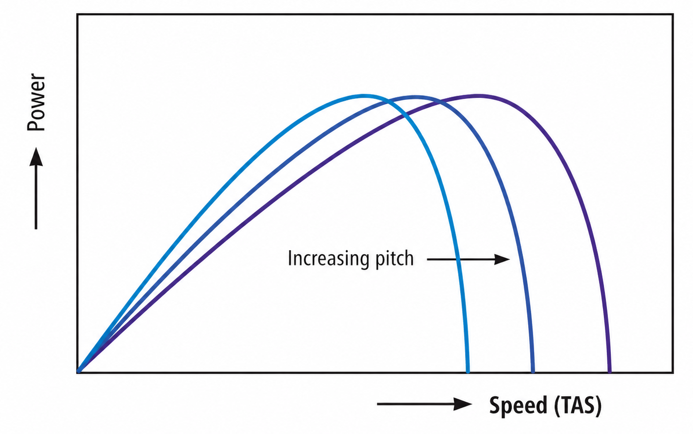
This is the case for a fixed pitch propellor which only produces optimal thrust during a certain speed, dependent on the construction of the propellor. It works good during or climb or cruising but never both.
- Small blade angle: Fine pitch -> Optimal for climbing
- Big blade angle: Coarse pitch -> Optimal for cruise
Constant speed propellor planes
Aircraft manufactures thought of a clever idea to make propellors where the pilot can set the blade angle based on the flight phase, where they can decrease the AoA in climbing phases and increase the AoA during cruise to get the most out of the engine at all times. These planes are called constant speed propellors -> the propellors always rotate at a constant speed.
This gives the pilot 3 handles instead of two. Next to a throttle and mixture they alsy get a blue for this cause. With that handle you can set a desired propellor RPM where you still control the fuel inlet pressure (manifold pressure) with the black throttle.
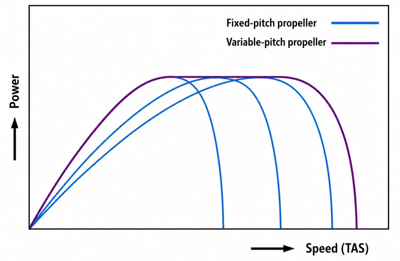
The graph shows that the line of a constant speed propellor is more flat and spanning the whole range. This means it can convert as much engine power to thrust as possible, and not only during climb or only during cruise.
You can see the constant speed propellor just like switching gears in a car. You can switch gears at all times to make the fuel efficiency better but also get higher speeds when you most need them.
Propellor side effects
The propellor is a great tool to produce straight forward motion called thrust. But the propellor also causes some aerodynamic side effects:
- Slipstream effect: The effect that turns around the plane and pushes against the rudder
- P-factor (assymmetric blade-effect): The assymmetric power the prop delivers at high angles of attack
- Torque effect: The effect of the plane wanting to counteract the propellor movement
Let’s dive deeper into these three effects and how to take them into account as pilot and ultimately counteract them.
Slipstream-effect
The slipstream effect on single engine planes is caused by the right-rotating prop (seen from the cockpit). This slipstream rotates around the longtitudinal axis of the plane and hits the vertical stabilizer and rudder. During climbing situations, this results in a yawing motion to the left as the right-turning air hits the vertical stabilizer on the left side.
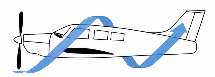
Aircrafts are designed to somewhat suppress this effect by assymmetric stabilizers, setting this under a small angle or a small ground adjustable trim surface on the rudder.
If we set a lower RPM, the slipstream becomes way less and then aircraft designs tend to yaw right. This is why we learn in single engine planes to counteract this effect as following:
- High RPM: Right rudder
- Low RPM: Left rudder
Think of: Low is Left or Left is Low.
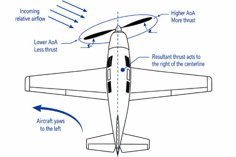
P-factor
The P-factor or assymmetric blade-effect with right rotating prop as seen from the cockpit is caused when a propellor that rotates is not perpendicular (loodrecht) to the flying direction. The downward blade produces more thrust than the upward blade. At high angles of attack, the downward blade moves in the flying direction but the upward blade moves opposite to the flying direction. The downward blade gets a higher AoA where the upward blade AoA decreases, and as we just learned that a higher AoA procudes more trust, we get asymmetrical thrust. The actual result is the nose of the plane wanting to go left.
This is the somewhat strange cause of why we need to give some right rudder in a left climbing turn.
Torque effect
The torque effect is exactly how it sounds, a rotating propellor produces a torque/rotating effect. We have to agree with mr. Newton again because this is an effect of his 3rd law; “For every action (force) in nature, there is an equal and opposite reaction”
The action is the propellor turning and the reaction is the fuselage of the plane wanting to roll left. This is mostly noticable during the take-off phase. The plane wants to roll left, resulting in more drag and force on the left wheel. The torque effect is therefore the same direction as the slipstream effect and increases the tendancy of the plane to go left.
During take-offs or touch and go’s, counteract by steering somewhat right with the rudder.
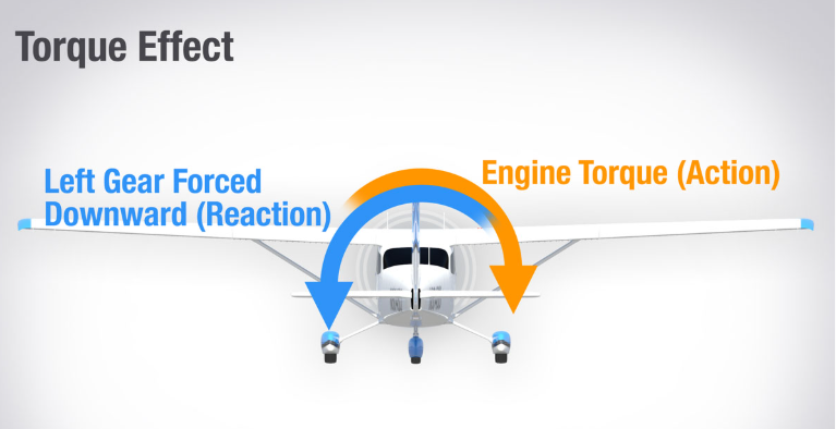
Source: Boldmethod.com
Stability (8)
An aircraft is continiously exposed to different attitude changes as result of wind, turbulence, convection or smaal yoke inputs. After being exposed to such change the forces and moments on the plane wordt not be balanced causing a huge workload for the pilot. Flying must be fun and easy to do, the easier it is, the safer.
An aircraft has great control-properties if its stabilityis good. With stability we mean that the plane must restore itself to the balance state after a small change, apart from if this change is intentional or not. Stability also has some downsides, when turning or maneuvering we are changing the attitude of the plane and makes this somewhat harder. Aircraft manufacturers seek to find the perfect balance between stability and maneuvering.
Types of stability
We can have three types of stability:
- Statically unstable
- Neutral (indifferential)
- Statically stable
Some examples of how this looks:
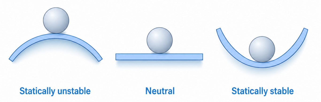
As we can think of the mass of the ball and the gravity working against themselves, in the statically stable situation, the ball would move around somewhat and then return to the before point when moving. This makes it statically stable.
The ball on the left would after moving never reach its stability point. The middle ball will constantly pick a new balancing point, but will need continuous corrections.
Dynamic stability
The dynamic stability describes the flow of the three situations above into the speed of returning to the balancing point and thus being stable. When a plane’s attitude is changed during cruise flight where all 4 flying forces are balanced, the plane must return to that balancing point as soon as possible. We can only achieve dynamic stability if the plane is statically stable.
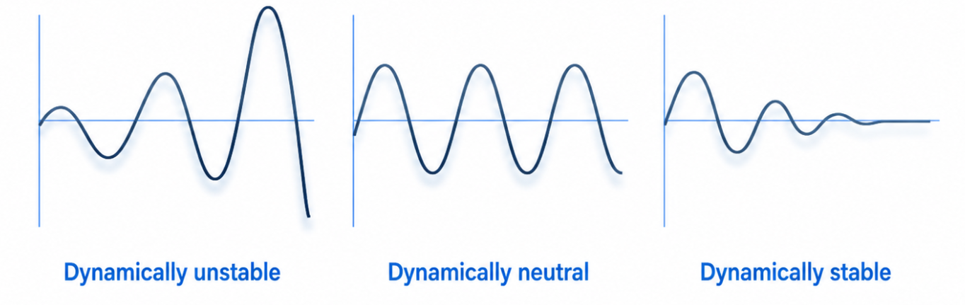
Aircraft stability and axis
| Axis | Axis (Dutch) | Stability | Stability (Dutch) | Movement |
|---|---|---|---|---|
| Longitudinal axis | Langsas | Lateral stability | Dwarsstabiliteit | Pitch |
| Vertical axis | Topas | Directional axis | Richtingsstabiliteit | Yaw |
| Lateral axis | Dwarsas | Longitudinal stability | Langsstabiliteit | Roll |
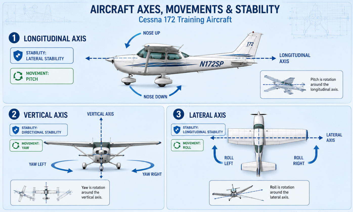
Longitudinal stability
The longitudinal stability is the stability of the lateral axis, the pitch movement. An aircraft is longitudinal stable if the it restores the pitch (AoA) to the state before interruption like minor inputs, wind or turbulence. Planes are designed that the center of gravity (CG) lies in front of the Center of Lift (Center of Pressure). This is by design to make the plane making a nose up movement when throttle is full and a nose down movement when throttle is closed. The slipstream air of the propellor flows over the elevator making it very effective.
To compensate for this moment and to make the plane longitudinal stable, we have the horizontal stabilizer at the tail of the plane. This is basically an upside down wing at the tail of the plane, and is an extra lift factor which makes the plane more stable on the longitudinal axis (langsas).
When the center of gravity (CG) is in front of the Center of Lift, (pressure point), the horizontal stabilizer must do a negative force. Because of the distance between CG and horizontal stabilizer is much longer than between CG and pressure point, a small horizontal stabilizer moment is needed. This distance defines operationally how stable the plane is on the longitudinal axis, the more the CG is up front, the more stable the plane is. If this CG shifts backward, then the stability decreases.
Canard
A canard is a set of small wings at the nose of the plane. Some planes counteract the longitudinal stability by shifting the wings somewhat to the back. This creates a more frontal CG in combination with this added set of small wings. These canards always produce positive lift as the AoA is positive.
Center of Gravity boundaries
As the CG has a big impact on the stability of the plane, the allowed position of the center of gravity is strictly limited. This CG must be within a limited frontal and after CG. Exceeding this values can dramatically decrease stability and flight performances.
- Too Frontal CG : This makes the plane stable but requires bigger steering forces. This can also lead to being unable to perform a roundout during landing.
- Too Aft CG: If the CG is more to the tail of the plane, the longitudinal stability is relatively small. The pilot must continuously correct the pitch resulting in uncontrolled pitch up movements.
The most aft limit of the center of gravitity is still in front of the Center of Lift by design, but mind to do your Mass and Balance calculations the right way to prevent those crazy things from happening.
Horizontal Stabilizer AoA
To get enough longitudinal stability, the horizontal stabilizer has a smaller angle of incidence and so AoA. This is done so every pitch change has a bigger effect on the horizontal stabilizer than on the wings. This angle of AoA of the wings and the horizontal stabilizer is called the long-V angle.
This difference in AoA also causes the wings to stall first in high nose up situations, making the elevator still controllable to recover.
Directional stability
The directional stability is the stability around the vertical axis (yaw). If during a flight the air comes straight head-on, the flight will be coordinated. If because of a small yaw imput the air will not come front, a slip occurs. We call the angle between the incoming air and the longitudinal axis the slipping angle.
An aircraft is directionally stable if during a slip it wants to recover itself to be aligned with the incoming air again. This is mostly achieved by the use of the vertical stabilizer. This also gets a different angle during slips, which result in an aerodynamic force from the side making the slip undone.
Effect of Center of Gravity
The distance between the vertical stabilizer and the CG (the arm) determines the directional stability. A more aft-CG will decrease the arm of the vertical stabilizer and making it less effective and so less stable. A more frontal CG does the opposite, increasing the effectivity and stability.
Lateral stability
The lateral stability is the rolling-axis stability. An aircraft is roll-stable when it returns to wings-level state after rolling. Just as the directional stability, is the roll stability a result of a slipping movement. Because of this movement another force occurs which restores the balance.
At lighter planes, this stability is reached by placing the wings under an angle of the longitudinal axis like a Piper plane. This is called a dihedral. If the wingtips are lower than the wing-root, then it would be called anhedral.
Such dihedral is dependent of a slipping movement where the airflow comes at an angle. This can happen when a plane rolls, the AoA of the lower wing will increased and the higher wing decreased resulting in a recovery to wings level.
Dihedral effect
A high-winger like a Cessna 172 has a better rolling stability than a low-winger like a Piper. The cause of this is in the behaviour of the crosswind-flow when a rolling motion.
The crosswind-flow will be bent off by the fuselage. At a high-winger this results in a bigger AoA of the low wing. This results in more life, pushing the low wing up and be balanced again.
Center of gravity details
A plane is behaving different when loaded differently. As we have an object that is flying through the air, it needs to be balanced which we do in the mass and balance sheet. It cannot exceed the forward or after limits, but based on how the plane is loaded, it will behave differently.
| Topic | Forward CG | Aft CG |
|---|---|---|
| Aircraft balance | Nose-heavy | Tail-heavy |
| Longitudinal stability | More stable | Less stable |
| Pitch control | Heavier control forces | Lighter control forces |
| Elevator authority | More elevator force needed | Less elevator force needed |
| Stall speed | Higher stall speed | Lower stall speed |
| Take-off/landing distance | Longer | Shorter |
| Landing flare | More difficult to flare | Easier to over-flare or balloon |
| Stall behaviour | Nose tends to drop more naturally | Nose may not drop as readily |
| Stall recovery | Easier recovery | More difficult recovery |
| Spin tendency | Less likely to enter a spin | More likely to enter a spin |
| Spin recovery | Generally easier | May be difficult or impossible |
| Drag | More drag, greater tail-down force | Less drag |
| Cruise performance | Worse cruise performance | Better cruise performance |
| Fuel consumption | Higher fuel consumption | Lower fuel consumption |
| Trim | More nose-up trim usually required | Less nose-up trim usually required |
| Main risk | Aircraft may not rotate or flare properly | Aircraft may become unstable or unrecoverable |
| Summary | Stable but heavy on controls | Efficient but unstable |
End of the page 🎉
You have reached the end of the page. You can navigate through other blog posts as well, share this post on X, LinkedIn and Reddit or return to the blog posts collection page. Thank you for visiting this post.
Support the blog
